
Decoding the Master Wiring Diagram for Car Audio Systems
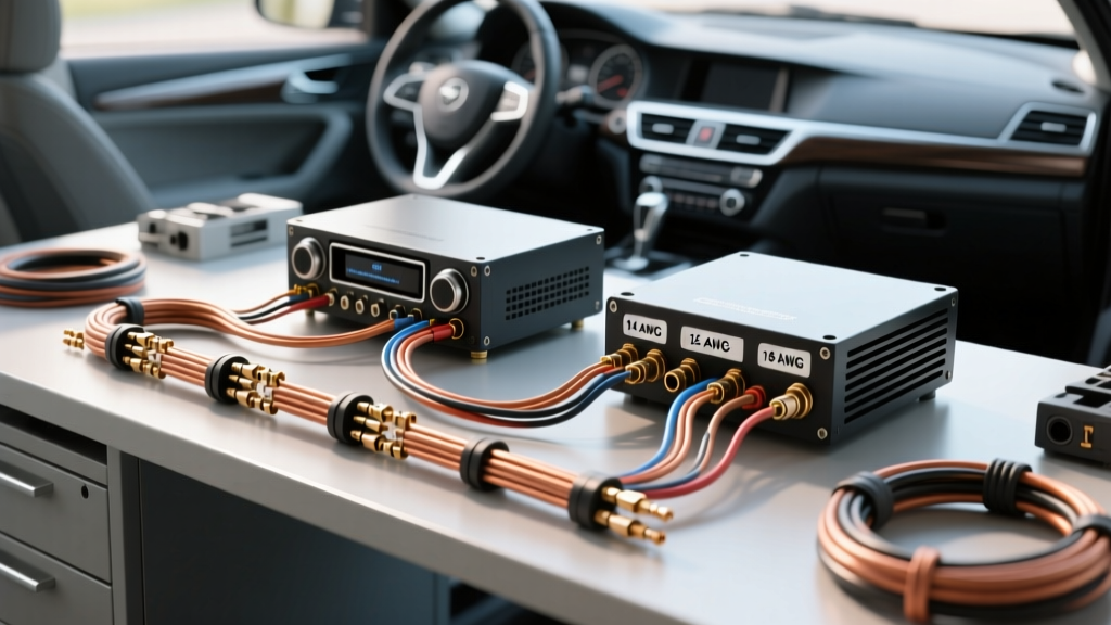
Designing and installing a high-fidelity mobile audio setup requires more than just connecting positive to positive. A proper wiring diagram for car audio system integration serves as the blueprint for signal integrity, power delivery, and component longevity. In 2026, with the rise of high-resolution digital signal processors (DSPs) and ultra-efficient Class D amplifiers, the margin for wiring errors has shrunk. Undersized power cables or improper grounding will instantly degrade audio quality and trigger protection circuits.
This comprehensive reference guide breaks down the exact wiring topology for a modern single-amplifier, multi-speaker car audio system, detailing specific wire gauges, routing protocols, and failure-mode troubleshooting.
The System Node Map: Power, Ground, and Signal
Before cutting a single zip-tie, you must understand the flow of current and signal. The table below maps the critical nodes in a standard head-unit-to-amplifier wiring diagram.
| Circuit Type | Source Node | Destination Node | Wire Specification | Industry Color Code |
|---|---|---|---|---|
| Main Power | Vehicle Battery (+) | Amplifier B+ Terminal | 4 AWG OFC Copper | Red (with inline fuse) |
| Main Ground | Amplifier GND Terminal | Vehicle Chassis (Bare Metal) | 4 AWG OFC Copper | Black |
| Remote Turn-On | Head Unit Harness | Amplifier REM Terminal | 18 AWG Stranded | Blue with White Stripe |
| Audio Signal | Head Unit RCA Outputs | Amplifier RCA Inputs | Shielded Twisted Pair | Red (Right) / White (Left) |
| Speaker Output | Amplifier Speaker Terminals | Component/Coaxial Speakers | 12 AWG OFC Stranded | Grey/Purple/Green/Blue |
The Power and Ground Circuit: Sizing and Routing
The power circuit is the foundation of your wiring diagram. According to the Crutchfield Amplifier Installation Guide, voltage drop is the leading cause of premature amplifier failure and clipped audio signals.
Wire Gauge Selection: OFC vs. CCA
When interpreting your wiring diagram, you must choose between Oxygen-Free Copper (OFC) and Copper-Clad Aluminum (CCA). CCA wire has higher electrical resistance. If you use CCA, you must step up one full wire gauge size to compensate for voltage drop. For a reliable 2026 installation, always specify 100% OFC wire.
- Up to 500W RMS: 8 AWG OFC Power Wire
- 500W - 1000W RMS: 4 AWG OFC Power Wire
- 1000W - 1500W RMS: 2 AWG OFC Power Wire
- 1500W+ RMS: 1/0 AWG OFC Power Wire
The 18-Inch Fuse Rule and Grounding Protocols
Your wiring diagram must include a main power fuse placed within 18 inches of the vehicle's positive battery terminal. This protects the vehicle from a catastrophic short circuit if the power wire chafes against the chassis. For systems drawing 60A to 120A, use an ANL (Automotive Noise Limiter) fuse rather than an AGU (Automotive Glass Tube) fuse, as AGU fuses are prone to internal arcing and failure under high continuous loads.
Expert Grounding Tip: The ground wire is not just a return path; it is the reference voltage for the amplifier's internal circuitry. Scrape away all factory paint, primer, and e-coat down to bare, shiny metal. Use a stainless steel bolt and a heat-shrink ring terminal. Finish by applying dielectric grease over the connection to prevent galvanic corrosion.
The Signal and Control Circuit: Eliminating Noise
The signal portion of the wiring diagram for car audio system setups is highly susceptible to Electromagnetic Interference (EMI). Modern vehicles are packed with CAN bus networks, EV inverters, and high-voltage switching lines that can induce severe noise into your audio path.
RCA Routing and the 90-Degree Rule
RCA cables carry low-voltage, unbalanced audio signals. If routed parallel to the 4 AWG power wire, the RCA cables will act as antennas, picking up alternator whine and inverter noise.
- Route the power wire down the driver's side of the vehicle.
- Route the RCA cables and speaker wires down the passenger side.
- If the signal wires must cross the power wire, ensure they cross at a strict 90-degree angle to minimize inductive coupling.
Remote Turn-On: Blue vs. Blue/White
A frequent DIY error occurs at the head unit harness. Most modern receivers (like the Pioneer DMH-W2770NEX or Alpine iLX-W650) feature two blue wires in the wiring diagram:
- Solid Blue Wire: Power Antenna. This wire only outputs +12V when the AM/FM radio tuner is active. If you connect your amplifier's remote turn-on to this wire, the amp will shut off when you switch to Bluetooth or USB.
- Blue with White Stripe: Amplifier Remote Turn-On. This wire outputs a steady +12V whenever the head unit is powered on, regardless of the source. Always use the Blue/White wire for the amplifier REM terminal.
2026 Component Spotlight & Budget Breakdown
To contextualize this wiring diagram, here is a highly rated, budget-conscious component list reflecting current 2026 market pricing for a 500W RMS system:
- Head Unit: Pioneer DMH-W2770NEX (Wireless CarPlay/Android Auto, 4V RCA preouts) — ~$349
- Amplifier: Rockford Fosgate R2-500X4 (Class D, 500W RMS, ultra-compact footprint) — ~$249
- Wiring Kit: Knukonceptz Kolossus 4 AWG OFC Complete Kit (Includes ANL fuse, RCA, and ring terminals) — ~$129
- Total Electronics & Wiring Budget: ~$727 (excluding speakers and labor)
Advanced Troubleshooting: When the Diagram Fails
Even with a perfect wiring diagram, physical installation variables can cause issues. Reference this troubleshooting matrix to diagnose common post-installation failures.
| Symptom | Probable Cause | Diagnostic Solution |
|---|---|---|
| High-pitched whine that rises with engine RPM | Ground loop or RCA cables running parallel to power. | Check amplifier and head unit grounds. Ensure both are grounded to clean, unpainted chassis metal. Reroute RCAs away from power. |
| Loud 'POP' from speakers when turning off the car | Head unit remote turn-on sequencing or DC offset. | Install a 1-second delay relay on the REM wire, or ensure the head unit's internal turn-off delay is enabled in the settings menu. |
| Amplifier goes into 'Protect' mode during heavy bass hits | Voltage drop due to undersized wire or weak battery. | Measure voltage at the amp B+ terminal during heavy bass. If it drops below 10.5V, upgrade to 2 AWG wire or add a 1.5 Farad capacitor / secondary AGM battery. |
| Only one channel plays audio | Blown RCA ground shield or unseated head unit connection. | Swap left and right RCA cables at the amplifier. If the dead channel moves, the issue is the head unit or the RCA cable itself. |
Expert Considerations for EV and Hybrid Vehicles
As of 2026, a significant portion of vehicles on the road are Electric Vehicles (EVs) or Plug-in Hybrids (PHEVs). The wiring diagram for car audio system upgrades in these vehicles requires special attention to the 12V auxiliary system. Unlike traditional internal combustion engine (ICE) vehicles that use a 100A+ alternator to recharge the 12V battery, EVs use a DC-DC converter.
Many EV DC-DC converters are strictly limited to 1200W to 1500W total output across the entire vehicle's 12V system. If your car audio system demands 100A (1200W) continuously, you risk tripping the vehicle's DC-DC converter protection, which will shut down critical vehicle electronics. For EV installations, utilize high-efficiency Class D amplifiers, add a dedicated lithium iron phosphate (LiFePO4) auxiliary audio battery with a battery isolator, and consult the AudioControl Car Audio Basics documentation for low-current draw DSP tuning strategies.
Frequently Asked Questions
Can I use the vehicle's factory wiring harness for amplifier power?
No. Factory wiring is typically 16 AWG to 18 AWG, designed only for the low current draw of a 15W x 4 factory head unit. Running a 500W amplifier through factory wires will cause severe voltage drop, melted insulation, and potentially an electrical fire. Always run a dedicated, fused power wire directly from the battery.
Do I need to disconnect the car battery before wiring?
Yes. Always disconnect the negative (-) terminal of the vehicle battery before cutting, stripping, or routing any power wires. This prevents accidental short circuits against the chassis while working with the main power cable.
What is the purpose of the 'Sense' or 'Remote Sense' wire on some amplifiers?
Found on high-end DSP amplifiers, the Remote Sense wire monitors the actual voltage at the amplifier's terminals and adjusts the internal power supply accordingly. If your amp has this feature, run an 18 AWG wire from the 'Sense' terminal directly to the vehicle's ignition switch or a clean +12V accessory fuse tap to ensure accurate voltage regulation.