
Single-phase induction motors are the undisputed workhorses of workshop air compressors, HVAC blowers, agricultural pumps, and heavy-duty table saws. Unlike three-phase motors that naturally generate a rotating magnetic field, single-phase motors require a mechanical or electrical phase shift to produce starting torque. If you are trying to wire a 1.5 HP Baldor-Reliance L1410TM or a Leeson C143T series motor, finding the correct wiring diagram for your specific capacitor configuration is the difference between a reliable machine and a melted winding.
In this comprehensive tutorial, we break down the exact terminal mappings, National Electrical Code (NEC) compliance requirements for 2026, and real-world troubleshooting steps for capacitor-start and capacitor-start/capacitor-run single-phase motors.
⚠️ SAFETY WARNING: Single-phase motors operating at 230V carry lethal voltage. Always verify the absence of voltage using a CAT III or CAT IV rated multimeter (such as the Fluke 117) before touching any terminal blocks. Capacitors can retain a dangerous charge even when power is disconnected; always discharge them with a 20k-ohm, 5-watt resistor before handling.Understanding the Internal Architecture
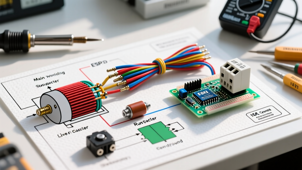
Before connecting external power, you must understand what happens inside the motor housing. A standard capacitor-start single-phase motor features two distinct sets of copper windings:
- Main (Run) Winding: Constructed with thicker wire and lower resistance. It remains energized continuously while the motor is running and provides the primary torque.
- Auxiliary (Start) Winding: Made of thinner wire with higher resistance. It is only designed for short-duty cycles (typically 3 to 5 seconds) and is connected in series with a start capacitor.
The Role of the Centrifugal Switch
When you apply power, both windings energize, creating the phase shift needed to spin the rotor. As the motor reaches approximately 75% of its rated RPM (usually around 1,300 RPM for a 1,725 RPM motor), a mechanical centrifugal switch mounted on the rotor shaft physically throws open. This disconnects the start winding and start capacitor from the circuit. If this switch fails to open, the start winding will overheat and burn out within seconds.
Standard NEMA Terminal Mapping (115V/230V Dual Voltage)
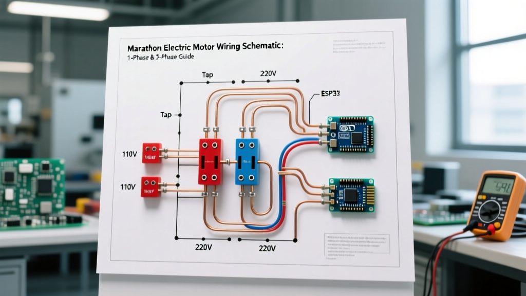
Most fractional and integral horsepower single-phase motors (up to 5 HP) are dual-voltage. The NEMA MG 1 standard dictates a specific numbering system for the external lead wires. Below is the universal terminal mapping for a standard 8-lead single-phase motor.
| Terminal | Internal Connection | Function |
|---|---|---|
| T1 | Main Winding Start | Line 1 (115V) or Line 1 (230V) |
| T2 | Start Winding / Switch | Connects to T3 (115V) or T8 (230V) |
| T3 | Main Winding Center Tap | Neutral (115V) or Jumper to T2 |
| T4 | Main Winding Finish | Neutral (115V) or Line 2 (230V) |
| T5 | Start Capacitor Lead 1 | Connects to T2 (via switch) |
| T8 | Start Capacitor Lead 2 | Connects to T3 (115V) or T2 (230V) |
Pro Tip: Always verify the factory-supplied diagram located on the inside of the motor's conduit box cover. Manufacturers occasionally use proprietary color codes for unmarked pigtails that deviate from standard NEMA numbering.
Step-by-Step Wiring Guide for 230V Operation
Wiring for 230V is highly recommended for motors 1 HP and above. It halves the amperage draw, reduces voltage drop over long wire runs, and allows for the use of smaller gauge copper wire—a critical cost-saving measure given that copper prices in early 2026 are averaging over $4.10 per pound.
Step 1: Configure the Internal Jumpers
- Connect T2 and T3 together. This places the start winding in series with the main winding's center tap.
- Connect T5 and T8 to the external start capacitor. (If your motor also features a run capacitor, it will typically wire in parallel with the main winding, bypassing the centrifugal switch).
Step 2: Select Wire Gauge and Breaker Sizing
Sizing the breaker for a motor is fundamentally different from sizing one for a resistive load like a heater. According to NFPA 70 (NEC) Article 430.52, the instantaneous inrush current (Locked Rotor Amps, or LRA) of a single-phase motor can be 6 to 8 times its Full Load Amps (FLA).
For a 1.5 HP, 230V motor with an FLA of 10.4A:
- Wire Size: 12 AWG THHN copper (Rated for 20A minimum, but NEC 240.4(D) small conductor rules apply. For motor circuits, we size based on 125% of FLA: 10.4 x 1.25 = 13A. 14 AWG is technically legal but 12 AWG is the professional standard for voltage drop mitigation).
- Breaker Size: NEC allows an inverse-time breaker to be sized up to 250% of the FLA to prevent nuisance tripping during startup. 10.4A x 2.5 = 26A. Therefore, a 25A or 30A double-pole breaker is correct. Do NOT use a 15A breaker; it will trip instantly upon startup.
2026 Component Sourcing and Pricing
When replacing failed components or building a custom control panel, sourcing high-quality capacitors and contactors is vital. Cheap, imported capacitors often fail prematurely due to inferior dielectric fluids and weak pressure-interrupter switches.
| Component | Recommended Brand/Model | 2026 Avg. Price | Lifespan Expectancy |
|---|---|---|---|
| Start Capacitor (189-227 µF) | Genteq 27L Series | $14.00 - $19.00 | 5+ Years (Short Duty) |
| Run Capacitor (30 µF / 440V) | AmRad PRO (Titan Series) | $18.00 - $24.00 | 10+ Years (Continuous) |
| Definite Purpose Contactor | Siemens 3RT2015 | $45.00 - $65.00 | 1,000,000+ Cycles |
Troubleshooting Common Failure Modes
Even with a perfect wiring diagram, single-phase motors are subject to specific mechanical and electrical failures. Here is how to diagnose the three most common issues using a digital multimeter (DMM).
1. Motor Hums but Will Not Start (Thermal Overload Trips)
The Culprit: 90% of the time, this is a failed start capacitor or a stuck centrifugal switch. If the start cap cannot provide the necessary phase shift, the motor acts like a transformer, drawing massive locked-rotor current without rotating.
The Fix: Disconnect power. Discharge the start capacitor. Set your Fluke multimeter to the capacitance (µF) setting. A reading more than 10% below the rated microfarads on the label means the capacitor is dead. If the capacitor tests fine, manually actuate the centrifugal switch weights by hand to ensure they move freely and aren't clogged with sawdust or grease.
2. Motor Starts but Runs Hot and Noisy
The Culprit: A degraded run capacitor (on capacitor-start/capacitor-run models) or incorrect voltage tap connections.
The Fix: If wired for 230V but accidentally tapped for 115V, the motor will run, but it will draw double the amperage and overheat rapidly. Verify your T1-T4 jumper configuration against the nameplate. Next, test the run capacitor. Run capacitors use a metallized polypropylene film that slowly degrades over time, losing capacitance and causing the auxiliary winding to overheat during continuous operation.
3. Breaker Trips Instantly Upon Energizing
The Culprit: Dead short in the main winding, or a seized rotor bearing.
The Fix: Remove the drive belt to isolate the motor from the load. Spin the shaft by hand. If it feels gritty or binds, the bearings are shot. If it spins freely, use your DMM in resistance (Ohms) mode to measure between T1 and T4. A reading near 0.0 ohms indicates the internal enamel insulation has melted, shorting the windings together. The motor must be rewound or replaced.
Summary Checklist for a Safe Installation
- Verify nameplate FLA and Voltage requirements before stripping wires.
- Confirm wire gauge meets NEC 125% continuous load rules for motor circuits.
- Ensure the grounding lug is bonded to a continuous equipment grounding conductor (EGC), never relying on the conduit alone for high-vibration equipment.
- Test capacitor health with a dedicated capacitance meter before installing, even if the part is brand new out of the box.
By understanding the internal mechanics and strictly adhering to the NEMA terminal mappings, you can confidently wire, troubleshoot, and maintain single-phase induction motors for decades of reliable service.