
The "Fuse Box" Misnomer and Modern Reality
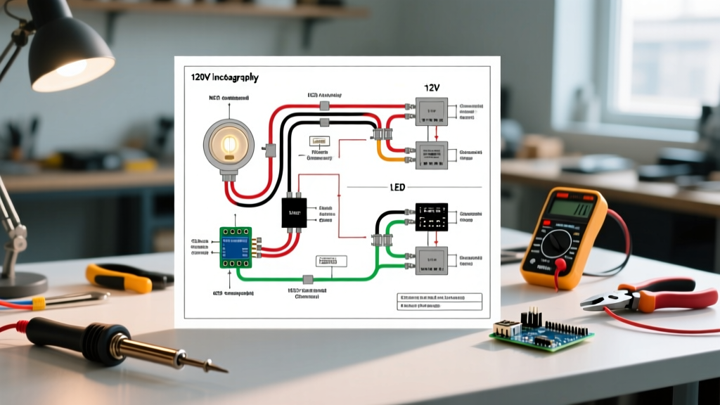
When homeowners and junior electricians search for a wiring diagram for fuse box configurations, they are usually dealing with one of two scenarios: maintaining a legacy Edison-base or Type-S fuse panel in a pre-1965 home, or planning an upgrade to a modern circuit breaker load center. In 2026, true fuse panels are considered obsolete by insurance underwriters and the National Electrical Code (NEC). They lack the rapid trip-curve response of modern thermal-magnetic breakers and are highly susceptible to the dangerous practice of "over-fusing" (e.g., placing a 30A fuse on 14 AWG wire).
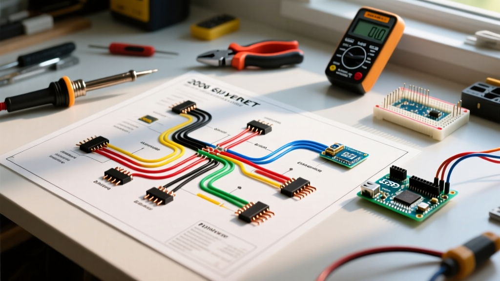
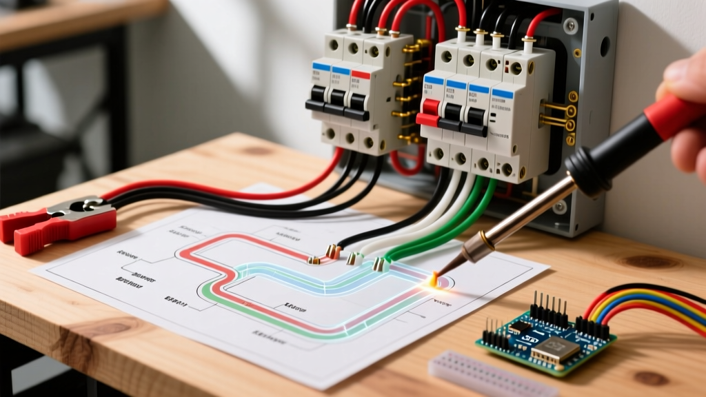
This step-by-step walkthrough translates the core concepts of a legacy fuse panel wiring schematic into a modern 200-Amp Main Breaker Panel (using the industry-standard Square D QO series as our reference model). Whether you are studying for your journeyman exam or planning a heavy-up service upgrade, understanding the transition from fused disconnects to a modern load center is critical for safety and code compliance.
Anatomy of a 200-Amp Main Breaker Panel
Before touching a single conductor, you must understand how the modern load center improves upon the old fuse box. A modern panel separates the hot bus bars, the neutral bar, and the equipment grounding bar, allowing for precise fault clearing.
| Feature | Legacy Fuse Box (Edison/Type-S) | Modern 200A Breaker Panel (Square D QO) |
|---|---|---|
| Overcurrent Protection | Screw-in fuses (slow blow/fast blow) | Thermal-magnetic miniature circuit breakers (MCBs) |
| Max Service Capacity | 60A to 100A (typically) | 200A to 400A (standard residential) |
| Ground Fault/Arc Protection | None | AFCI and GFCI integration at the breaker level |
| Bus Bar Material | Copper (often exposed/degraded) | Plated Aluminum or Copper (fully shielded) |
| Approx. 2026 Material Cost | N/A (No longer manufactured) | $160 - $240 (Panel enclosure + main breaker) |
Step-by-Step Wiring Walkthrough: Translating the Diagram
Follow this sequential wiring workflow to properly terminate a modern 200-Amp main service panel. Disclaimer: Working inside a main service panel exposes you to lethal utility-side voltage that cannot be shut off without pulling the utility meter. This guide is for educational reference; always hire a licensed contractor for live service work.
Step 1: Service Entrance Conductors & Main Lugs
In a legacy fuse box, the service drop wires (often 2 AWG copper for 100A) terminated directly into the main fused disconnect. In a modern 200A upgrade, you will pull 2/0 AWG Copper or 4/0 AWG Aluminum service entrance conductors from the meter base to the main panel lugs.
- Preparation: Strip exactly 1.25 inches of insulation from the conductor ends. Do not nick the copper or aluminum strands.
- Anti-Oxidant: If using 4/0 Aluminum, you must apply a UL-listed anti-oxidant compound (like Noalox) to the exposed strands before insertion to prevent galvanic corrosion and high-resistance heating over time.
- Termination: Seat the conductors fully into the main lugs. The hot legs (Phase A and Phase B) land on the outer main lugs, while the neutral lands on the center lug or designated neutral bus.
Step 2: The Neutral-to-Ground Bond (Crucial Edge Case)
The most common point of failure in panel wiring is misunderstanding the neutral-to-ground bond. According to NFPA 70 (NEC) Article 250.24, the neutral and ground must be bonded only at the first point of disconnect (the main service panel).
Critical 2026 Code Reminder: If you are wiring a subpanel (e.g., for a detached garage or EV charger), you must remove the green bonding screw or strap. Mixing neutrals and grounds on the same bus bar in a subpanel creates a parallel neutral path, energizing the grounding system and creating a severe shock hazard.
Step 3: Branch Circuit Routing & AFCI/GFCI Compliance
Legacy fuse boxes utilized simple wire-routing: hot to fuse, neutral to bus, no ground. Modern diagrams require strict adherence to AFCI (Arc-Fault Circuit Interrupter) and GFCI (Ground-Fault Circuit Interrupter) mandates.
- Kitchens & Bathrooms: Route 12 AWG copper to 20A GFCI breakers. All countertop receptacles must be GFCI protected.
- Living Spaces & Bedrooms: Route 14 AWG (15A) or 12 AWG (20A) to Combination-Type AFCI breakers. In 2026, AFCI protection is required for virtually all 120V, 15A and 20A branch circuits supplying living areas.
- 240V Appliances: Electric ranges and dryers require 4-wire connections (Hot, Hot, Neutral, Ground). Never use a 3-wire legacy configuration for new installations.
Torque Specifications and Thermal Failure Modes
Loose connections are the leading cause of electrical fires in panelboards. The NEC (Article 110.14) now strictly mandates that all terminations be torqued to the manufacturer's specifications using a calibrated torque screwdriver or torque wrench. Guessing the tightness by "feel" is a code violation and a massive liability.
| Termination Point | Wire Gauge | Required Torque (Square D QO) | Failure Mode if Under-Torqued |
|---|---|---|---|
| Main Service Lugs | 2/0 Cu / 4/0 Al | 250 in-lbs (20.8 ft-lbs) | Thermal runaway, lug melting, utility-side arcing |
| Neutral / Ground Bus | #4 to #14 AWG | 45 in-lbs | Stray voltage on grounding paths, neutral drift |
| Branch Breaker Lugs (15-30A) | #14 to #10 AWG | 35 in-lbs | Breaker pigtail overheating, false tripping |
| Branch Breaker Lugs (40-50A) | #8 to #4 AWG | 45 in-lbs | Insulation melt-back, short circuit to panel chassis |
3 Fatal Wiring Mistakes to Avoid
When transitioning from the mindset of an old wiring diagram for fuse box setups to modern breaker panels, avoid these catastrophic errors:
1. Double-Tapping on Non-Rated Lugs
Placing two wires under a single breaker lug or neutral bus screw is a direct violation of NEC 110.14(A) unless the lug is explicitly listed and marked for multiple conductors. Square D QO breakers typically allow two wires on the neutral/ground bar, but never on the hot breaker terminal. Use a pigtail wire nut connection or a dedicated twin-breaker instead.
2. Over-Torquing Aluminum Lugs
While under-torquing causes arcing, over-torquing aluminum service wires causes the soft metal to "cold flow" or crush. This permanently deforms the conductor, reducing its cross-sectional area and creating a high-resistance hot spot that will eventually fail under heavy load (like an EV charging session or HVAC startup).
3. Mixing Ground and Neutral on Branch Circuits
In a fuse box, the metal chassis often served as the ground return (a dangerous, banned practice). In a modern panel, the equipment grounding conductor (bare copper or green) and the grounded neutral conductor (white) must remain strictly separated once they leave the main bonding jumper. A bootleg ground or neutral-to-ground short downstream will cause GFCI and AFCI breakers to trip immediately and prevent proper fault clearing.
References and Further Reading
For the most current safety standards and installation practices, always consult the latest editions of the following resources:
- National Fire Protection Association (NFPA 70: National Electrical Code) - The definitive standard for all US electrical installations, updated on a 3-year cycle.
- Occupational Safety and Health Administration (OSHA) Electrical Safety Guidelines - Crucial for understanding lockout/tagout (LOTO) and arc flash boundary requirements during panel upgrades.
- U.S. Consumer Product Safety Commission (CPSC) Electrical Fire Safety - Data and reports on residential electrical fires caused by legacy fuse panels and improper DIY wiring.
Disclaimer: Electrical work carries inherent risks of shock, arc flash, and fire. This guide is intended for educational purposes. Always verify local amendments to the NEC and obtain necessary permits before beginning any service upgrade.