
The Complexities of Mobile Laundry: Beyond Residential Standards
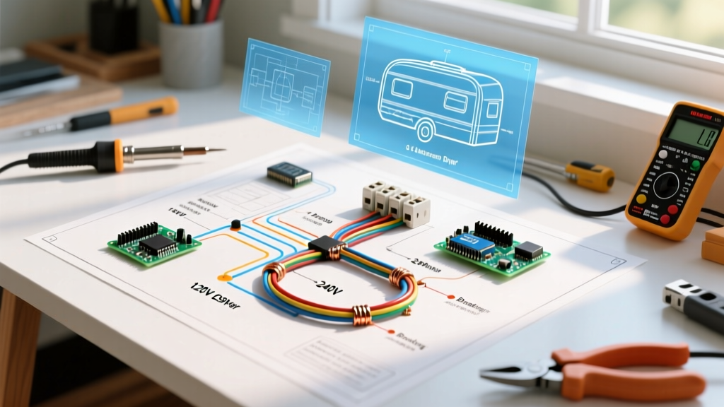
Integrating a laundry system into a Class A motorhome, fifth-wheel toy hauler, or custom camper van requires a fundamental shift from standard residential electrical practices. When you are searching for a reliable wiring diagram for dryer applications in a vehicle, you must account for chassis vibration, strict weight limitations, and the unique split-phase or pure 120V topologies of RV shore power. In 2026, with the rise of high-capacity lithium arrays and advanced inverter-chargers like the Victron Quattro, off-grid mobile laundry is more viable than ever, but the electrical infrastructure must be flawless to prevent catastrophic thermal events.
CRITICAL CODE WARNING: Under NEC Article 551.48 and RVIA standards, solid-core Romex (NM-B) cable is strictly prohibited in mobile applications subject to road vibration. You must use stranded THHN/THWN wire routed through flexible Liquid-Tite conduit or approved stranded mobile home cable to prevent work-hardening and eventual conductor fracture.
RV Power Topologies: Matching the Dryer to the Chassis
Before pulling any wire, you must identify your RV's shore power configuration and inverter capabilities. The wiring diagram for dryer units changes drastically based on whether your rig is equipped with a 30-amp or 50-amp main service panel.
1. The 30-Amp RV System (120V Only)
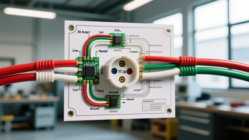
A standard 30-amp RV plug (NEMA TT-30) delivers a maximum of 3,600 watts at 120V. You cannot run a traditional 240V residential dryer on this system. Your only options are 120V ventless washer/dryer combos (like the Splendide WD2100XC) or 120V/gas hybrid dryers. These require a dedicated 20-amp, single-pole breaker and 12 AWG stranded wire.
2. The 50-Amp RV System (120/240V Split-Phase)
A 50-amp RV service (NEMA 14-50) actually provides two 120V legs (L1 and L2) with a shared neutral, yielding 240V across the two hot legs. This allows you to install a standard 240V residential dryer (like the LG WM3998HBA) or a high-speed 240V vented unit, provided your main distribution panel supports 2-pole breakers and your generator/inverter can handle the 240V split-phase load.
Dryer Electrical Requirements & Sizing Matrix
Use the following matrix to determine the correct wire gauge, breaker sizing, and receptacle type for the most common RV dryer installations in 2026.
| Dryer Model / Type | Voltage | Max Amperage | Wire Gauge (Stranded) | Breaker Type | Receptacle |
|---|---|---|---|---|---|
| Splendide WD2100XC (Ventless Combo) | 120V AC | 11A - 15A | 12 AWG THHN | 1-Pole 20A | NEMA 5-20R |
| LG WM3998HBA (240V Combo) | 240V AC | 27A | 10 AWG THHN | 2-Pole 30A | NEMA 14-30R |
| Girard RV Gas Dryer | 120V AC (Motor) | 3A | 14 AWG THHN | 1-Pole 15A | NEMA 5-15R |
| Off-Grid 120V Inverter Setup | 120V AC | 15A (Heater) | 12 AWG THHN (AC) / 2/0 AWG (DC) | 1-Pole 20A (AC) | NEMA 5-20R |
Step-by-Step: 50-Amp RV Wiring Diagram for Dryer (240V Setup)
If you are upgrading a luxury motorhome to accommodate a 240V dryer, the circuit must be isolated from standard 120V appliance circuits to prevent neutral overload. Here is the exact wiring path from the main panel to the receptacle.
- Main Distribution Panel: Install a 2-pole 30A breaker (e.g., Square D QO230 or Siemens QT230, depending on your RV's panel brand). Ensure it snaps across both the L1 and L2 bus bars to pull 240V.
- Conduit Routing: Route 1/2-inch Liquid-Tite flexible metallic conduit from the panel to the dryer bay. Secure it with cushioned P-clamps every 18 inches to prevent chassis vibration from transferring to the wire insulation.
- Wire Pulling: Pull four strands of 10 AWG stranded THHN: Black (Hot L1), Red (Hot L2), White (Neutral), and Green (Ground). Note: Do not exceed the 40% conduit fill ratio per NEC Chapter 9.
- Receptacle Termination: Terminate the wires into a NEMA 14-30R receptacle mounted in a weatherproof, flush-mount RV bay box. Torque the terminal screws to exactly 12-15 in-lbs to prevent arcing under heavy motor startup loads.
- Grounding Bond: The Green ground wire must terminate on the main AC grounding bus bar in the distribution panel, which is bonded to the RV chassis. Never bond the neutral wire to the chassis.
Off-Grid Inverter Wiring: Running a 120V Dryer on Lithium
For boondockers and van-lifers in 2026, running a 120V ventless dryer off a massive lithium-iron-phosphate (LiFePO4) battery bank is the ultimate off-grid luxury. However, the DC-side wiring is just as critical as the AC-side diagram.
The Victron MultiPlus / Quattro Topology
To run a 120V dryer pulling 1,400 watts continuously, you need a minimum 3000W inverter. If you are using a Victron MultiPlus 12/3000, the DC wiring from the battery busbars to the inverter must be massive to handle the 120+ amp DC draw.
- DC Wire Gauge: Use 2/0 AWG stranded welding cable for runs up to 5 feet. If the battery bank is more than 10 feet away, step up to 4/0 AWG to prevent voltage drop below 11.5V, which will trigger the inverter's low-voltage cutoff mid-cycle.
- DC Fusing: Install a 400A Class T fuse (not an ANL fuse) within 18 inches of the battery positive terminal. Class T fuses have the high interrupting capacity (AIC) required for large lithium banks in the event of a dead short.
- AC Output Wiring: From the inverter's AC-Out terminal block, run 12 AWG stranded wire to a dedicated 20A sub-panel, then to your NEMA 5-20R dryer receptacle.
Common Edge Cases & Failure Modes in RV Dryer Wiring
Even with a perfect wiring diagram for dryer setups, mobile environments introduce unique failure modes that residential electricians rarely encounter.
1. Neutral Wire Overheating in Split-Phase Panels
In a 50-amp RV, the neutral bus bar carries the unbalanced current between L1 and L2. If you wire a 240V dryer and simultaneously run a 1500W microwave on the same leg, the neutral can become overloaded if the panel's neutral bus isn't rated for the combined amperage. Always verify the main neutral lug is torqued to the manufacturer's specification (usually 20-25 in-lbs for 6 AWG to 2/0 AWG feed wires).
2. Chassis Ground Loops
A frequent DIY mistake is grounding the dryer's green wire directly to a nearby metal frame rail instead of running it back to the main AC ground bus. This creates a ground loop. When the dryer's motor kicks on, stray AC current can travel through the RV's 12V DC chassis ground, frying sensitive CAN-bus networks, solar charge controllers, or multiplexing boards like the Vegatron or Firefly systems.
3. Terminal Vibration Loosening
Road harmonics will loosen standard screw terminals over time. In 2026, best practice dictates using ferrule crimps on all stranded THHN wires before inserting them into breaker and receptacle screw terminals. This prevents the 'bird-caging' of stranded wire and ensures a gas-tight connection that resists vibration-induced thermal runaway.
Code Compliance and Authoritative Standards
When modifying the electrical system of a motorized or towable RV, adherence to established safety codes is non-negotiable for both fire safety and insurance validity. The National Fire Protection Association (NFPA) outlines specific mobile electrical requirements in NEC Article 551, which governs recreational vehicles and RV parks. Furthermore, the Recreation Vehicle Industry Association (RVIA) mandates strict testing and wiring protocols for all factory-installed and aftermarket integrated appliances to ensure they can withstand the rigors of highway travel and extreme temperature fluctuations.
By following this specialized wiring diagram for dryer configurations, utilizing stranded conductors, and respecting the unique load-balancing requirements of RV power systems, you can safely enjoy the comforts of home laundry regardless of where the road takes you.