
Decoding the Wiring Diagram for a Garage Subpanel
Modern garages have evolved from simple storage spaces into high-demand electrical environments. Whether you are installing a Level 2 EV charger, running a 240V MIG welder, or powering a heavy-duty air compressor, relying on a single 120V extension cord from the house is a fire hazard. A proper wiring diagram for a garage dictates the installation of a dedicated subpanel. This guide breaks down the exact anatomy, component sizing, and National Electrical Code (NEC) requirements for wiring a 100-amp garage subpanel in 2026.
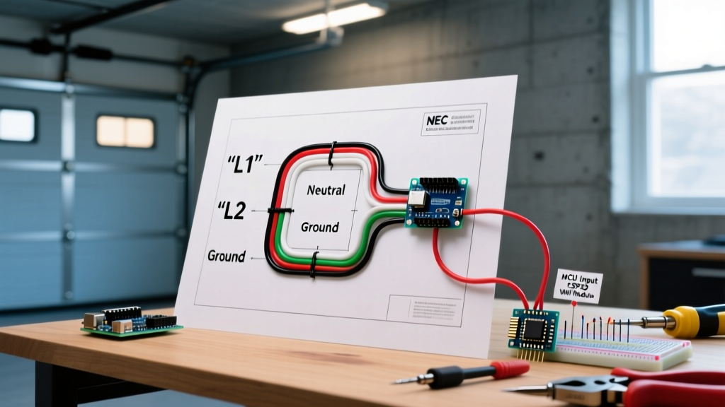
When reviewing a standard wiring diagram for a garage, the most critical junction is the feed from the main service panel to the detached or attached subpanel. The days of running a 3-wire feed and bonding the ground and neutral at the subpanel are long gone. Under current National Fire Protection Association (NFPA) guidelines, specifically NEC Article 250.32, all detached building subpanels require a strict 4-wire feed: two ungrounded conductors (hots), one grounded conductor (neutral), and one equipment grounding conductor (EGC).
Anatomy of the Main-to-Subpanel Feed
The core of your garage wiring diagram begins at the main panel's double-pole breaker and terminates at the subpanel's main lugs. Here is the exact path and specification for a standard 100-amp feed, which is the minimum recommended size for a modern garage to accommodate future EV charging and workshop tools.
1. The Overcurrent Protection Device (OCPD)
At the main house panel, you will install a 100-amp, 240-volt double-pole breaker. For a Square D Homeline panel, the exact model is the HOM2100CP (retailing around $48 in 2026). This breaker protects the entire feeder cable. If the garage is attached, standard thermal-magnetic breakers are sufficient. If the garage is considered a dwelling unit sleeping area (rare, but possible in ADU conversions), AFCI protection may be triggered, though standard subpanel feeds generally do not require AFCI at the feeder level.
2. Feeder Conductor Sizing and Selection
Choosing the right wire gauge is where many DIY diagrams fail. For a 100-amp subpanel feed, you must use conductors rated for at least 100 amps at a 75°C termination rating.
- Copper Option: 3 AWG THHN/THWN-2 copper wire. (Cost: ~$4.50 per foot per conductor).
- Aluminum Option: 1/0 AWG XHHW-2 or THWN-2 aluminum wire. (Cost: ~$2.10 per foot per conductor).
Because copper prices remain volatile and high in 2026, 1/0 AWG aluminum is the industry standard for residential subpanel feeds. You will pull four individual wires (Black, Red, White, and Green/Bare) through conduit.
3. Conduit Routing and Fill Capacity
According to NEC Chapter 9, Table 1, conduit fill cannot exceed 40% for three or more conductors. Four 1/0 AWG aluminum wires require a minimum of 1.25-inch PVC Schedule 80 conduit. However, professional electricians universally upgrade to 1.5-inch PVC to reduce pulling friction and allow for future heat dissipation. If the conduit is run underground to a detached garage, NEC Table 300.5 mandates a minimum trench depth of 18 inches for rigid metal conduit or 24 inches for PVC.
Component Sizing Matrix for Garage Subpanels
The table below provides a quick-reference matrix for sizing your garage subpanel components based on your specific amperage needs.
| Subpanel Size | Feeder Breaker | Copper Wire (THHN) | Aluminum Wire (XHHW-2) | Min. PVC Conduit | Estimated Material Cost |
|---|---|---|---|---|---|
| 60 Amp | 60A 2-Pole | 6 AWG | 4 AWG | 1 inch | $450 - $600 |
| 100 Amp | 100A 2-Pole | 3 AWG | 1/0 AWG | 1.25 inch (Use 1.5') | $750 - $1,000 |
| 125 Amp | 125A 2-Pole | 1 AWG | 2/0 AWG | 1.5 inch | $950 - $1,300 |
Note: Costs are based on early 2026 average retail pricing for wire, breakers, and a Square D HOM816L125TC (125A main lug, 8-space) subpanel enclosure.
Subpanel Internal Bus & The Bonding Rule
The most common—and dangerous—error when executing a garage wiring diagram is improperly bonding the neutral and ground bars inside the subpanel.
Critical NEC Warning: In a subpanel, the neutral (grounded) conductor and the equipment grounding conductor MUST remain strictly isolated. Bonding them together at the subpanel creates a parallel neutral path, meaning return current will flow through the ground wire, the conduit, and any connected metal appliances, creating a severe shock and fire hazard.
When you purchase a subpanel like the Siemens P0816L1125CU, it ships with a green bonding screw or a bonding strap pre-installed. You must remove this screw or strap. The white neutral wires must land exclusively on the insulated neutral bar, and the bare/green ground wires must land exclusively on the chassis-bonded ground bar. If your panel does not include a separate ground bar, you must purchase an add-on bar (e.g., Square D HOMCGK2C, ~$12) and attach it directly to the metal enclosure.
Branch Circuit Layouts: Mapping the Garage Interior
Once the feeder reaches the subpanel, your wiring diagram branches out into specific 120V and 240V circuits. A well-designed garage requires dedicated circuits for high-draw tools and GFCI protection for all receptacles.
120V General Lighting and Receptacles
- Lighting: Use 12 AWG copper wire on a 20-amp single-pole breaker. Wire LED high-bay fixtures (e.g., 150W, 20,000-lumen shop lights) in parallel. Do not put exterior security lights on the same switch as interior lights.
- Receptacles: Use 12 AWG copper wire on 20-amp breakers. Under the latest NEC 210.8(A)(2) rules, all 125-volt, single-phase, 15- and 20-ampere receptacles in a garage must have GFCI protection. You can achieve this by installing a GFCI breaker at the subpanel or using GFCI receptacles at the first outlet in the daisy chain.
240V Heavy Equipment and EV Charging
The 2026 electrical landscape is heavily focused on electrification. Your wiring diagram must account for 240V loads.
- Level 2 EV Charger: A standard 48-amp continuous EV charger (like the ChargePoint Home Flex or Tesla Wall Connector) requires a 60-amp breaker. Because EV charging is considered a 'continuous load' (running for 3+ hours), NEC Article 210.20(A) requires the breaker to be sized at 125% of the load. Use 6 AWG copper THHN wire. Crucial 2026 Update: NEC 210.8(F) now requires GFCI protection for 240V receptacles up to 50 amps. If you hardwire the EV charger, GFCI is generally not required, saving you $100+ on a specialized 240V GFCI breaker.
- Air Compressor / Welder: A standard 60-gallon, 5-HP air compressor typically draws 20-25 amps at 240V. Wire this with 10 AWG copper on a 30-amp double-pole breaker. Use a NEMA 6-30R receptacle.
Troubleshooting Common Garage Wiring Failures
Even with a perfect diagram, physical installation errors can cause system failures. Here are the most common edge cases we see in the field:
- Voltage Drop on Long Runs: If your detached garage is more than 150 feet from the main panel, a 100-amp feed using 1/0 AWG aluminum will experience noticeable voltage drop under heavy load (like starting a 5-HP compressor). Fix: Upsize the feeder wire to 2/0 AWG aluminum to keep voltage drop below the recommended 3% threshold.
- Loose Lug Connections: Aluminum wire expands and contracts more than copper under thermal load. If the 1/0 aluminum feeder lugs at the subpanel are not torqued to the manufacturer's exact specification (typically 45 in-lbs for Square D 100A lugs), the connection will arc, overheat, and melt the bus bar. Always use a calibrated torque screwdriver.
- Shared Neutrals (MWBC Errors): If you run a Multi-Wire Branch Circuit (MWBC) to save wire on 120V receptacles, the two hot wires must be on opposite phases (240V between them), and they must be tied together with a handle tie so they trip simultaneously. Failing to do this can overload the shared neutral wire, causing a fire inside the walls.
Frequently Asked Questions
Can I use direct burial wire instead of conduit for a detached garage?
Yes. If you are trenching to a detached garage, you can use UF-B or direct burial SER (Service Entrance Rated) cable. However, direct burial cable must be buried at least 24 inches deep, and it is highly susceptible to damage from future digging. Running individual THWN-2 wires inside a 1.5-inch PVC conduit remains the professional standard for longevity and future upgradability.
Does a detached garage subpanel need its own grounding rod?
Yes. According to NEC 250.32(B)(1), a detached building supplied by a feeder must have its own grounding electrode system. This typically means driving two 5/8-inch copper ground rods, spaced at least 6 feet apart, and connecting them to the subpanel's ground bar using a continuous 6 AWG bare copper grounding electrode conductor (GEC).
Do I need a main disconnect breaker at the garage subpanel?
NEC 225.31 requires a disconnecting means for a detached building. If your subpanel has 6 or fewer breakers, individual breakers can serve as the disconnect. However, if you install a panel with more than 6 spaces (which is highly recommended for a garage), you must install a panel with a main breaker (e.g., Square D HOM816M100C) rather than a main-lug-only panel, or install a separate disconnect switch outside the garage.
For further reading on grounding and bonding best practices, refer to the technical guides published by Electrical Contractor Magazine (ECM), which regularly breaks down complex NEC articles for field application. Always consult with a licensed master electrician and your local AHJ (Authority Having Jurisdiction) to ensure your specific garage wiring diagram meets all local amendments before pulling a permit.