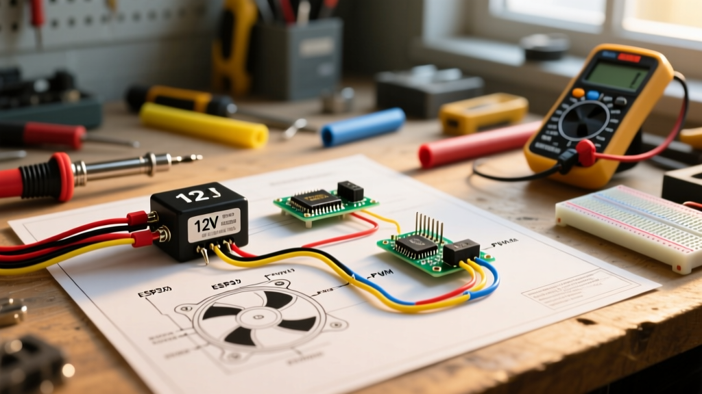

Introduction to High-CFM Appliance and HVAC Cooling Circuits
Whether you are building a custom liquid-cooling loop for an off-grid inverter, managing thermal loads in an EV battery enclosure, or retrofitting an HVAC condenser, understanding the correct wiring diagram for electric radiator fan setups is non-negotiable. High-performance 12V and 24V DC radiator fans—such as the industry-standard SPAL 30102044 (16-inch, 3000 CFM)—can draw upwards of 22 amps continuously, with inrush currents spiking past 40 amps upon startup. Direct-wiring these loads to a standard toggle switch or basic thermal probe will instantly melt the switch contacts and create a severe fire hazard.
As of 2026, the DIY and appliance repair communities have largely moved away from simple on/off thermal switches toward solid-state Pulse Width Modulation (PWM) controllers. However, the foundational logic of the relay-based wiring diagram for electric radiator fan circuits remains the baseline for all high-current DC thermal management. This guide breaks down the exact components, wire gauges, and circuit logic required to build a safe, code-compliant cooling system.
System Architecture: The Bill of Materials (BOM)
Before tracing the wiring diagram for electric radiator fan relays, you must source components rated for both the continuous amperage and the inrush current of your specific fan motor. Brushed DC motors require heavier fusing than modern brushless alternatives.
| Component | Recommended Model / Spec | Estimated 2026 Cost | Purpose |
|---|---|---|---|
| Radiator Fan | SPAL 30102044 (16' High Perf) | $165.00 | Primary airflow (3000 CFM, 22A draw) |
| Heavy-Duty Relay | Bosch 0 332 014 150 (40A, 5-Pin) | $14.50 | Isolates high-current load from control switch |
| Thermal Controller | Derale 16749 PWM Fan Controller | $145.00 | Variable speed control based on probe temp |
| Overcurrent Protection | 30A MAXI Fuse & Weatherpack Holder | $9.00 | Protects main power feed from short circuits |
| Primary Wiring | 10 AWG TXL (Cross-linked PE) | $0.85 / ft | Handles 30A+ with minimal voltage drop |
| Control Wiring | 16 AWG GXL | $0.45 / ft | Carries low-current trigger signal to relay |
Decoding the Wiring Diagram for Electric Radiator Fan Circuits
A standard wiring diagram for electric radiator fan setups utilizing a Bosch-style ISO mini relay divides the circuit into two distinct paths: the High-Current Power Feed and the Low-Current Control Logic. Understanding this separation is the key to troubleshooting and safe installation.
Phase 1: The High-Current Power Feed
The power feed handles the raw amperage required to spin the fan motor. This circuit bypasses the dashboard switch or thermal sensor entirely, relying on the relay's internal contactor to bridge the connection.
- Battery to Fuse: Run 10 AWG wire from the positive terminal of your 12V DC source to a 30A MAXI fuse holder. The fuse must be located within 6 inches of the power source to protect the entire downstream wire run.
- Fuse to Relay (Pin 30): Continue the 10 AWG wire from the fuse output to Pin 30 on the Bosch relay. Pin 30 is the common high-current input.
- Relay to Fan (Pin 87): Run a 10 AWG wire from Pin 87 (Normally Open contact) directly to the positive terminal on the electric radiator fan motor.
- Fan to Ground: Complete the power circuit by grounding the fan's negative terminal directly to the chassis or DC negative busbar using 10 AWG wire. Avoid daisy-chaining grounds with other high-draw appliances.
Phase 2: The Low-Current Control Logic
The control logic tells the relay when to close the high-current circuit. This side of the wiring diagram for electric radiator fan systems uses lighter gauge wire (16 AWG) because it only carries the fraction of an amp needed to energize the relay's internal electromagnet.
- Ignition/Switch to Thermal Controller: Run a 16 AWG wire from a switched 12V source (to prevent battery drain when the appliance or vehicle is off) to the 'Power In' terminal on your thermal switch or PWM controller.
- Controller to Relay (Pin 86): Run a 16 AWG wire from the 'Fan Trigger' output on your controller to Pin 86 on the relay. This provides the positive trigger signal.
- Relay Ground (Pin 85): Ground Pin 85 directly to the chassis or negative busbar. When the thermal controller sends 12V to Pin 86, the circuit completes through Pin 85 to ground, energizing the coil and snapping Pins 30 and 87 together.
Wire Sizing and Amperage Matrix
Undersized wiring is the leading cause of voltage drop in DC cooling systems. A voltage drop of just 1.5V at the fan motor will reduce CFM output by up to 20% and cause the motor to overheat. According to standard wire sizing guidelines based on NEC ampacity tables, you must size your wire based on the maximum continuous draw plus a 20% safety margin, factoring in the total round-trip length of the wire.
| Fan Amperage (Continuous) | Max Wire Length (Round Trip) | Minimum Wire Gauge (AWG) |
|---|---|---|
| 0 - 10 Amps | Up to 15 feet | 14 AWG |
| 10 - 20 Amps | Up to 15 feet | 12 AWG |
| 20 - 30 Amps | Up to 15 feet | 10 AWG |
| 20 - 30 Amps | 15 to 25 feet | 8 AWG |
| 30 - 40 Amps | Up to 15 feet | 8 AWG |
Advanced Integration: PWM vs. Standard Relay Control
While the traditional relay-based wiring diagram for electric radiator fan setups is reliable, it operates on a binary 'bang-bang' control logic. The fan is either 100% ON or 100% OFF. This creates massive current spikes, acoustic noise, and temperature oscillation (hysteresis).
In modern 2026 appliance and HVAC builds, PWM (Pulse Width Modulation) controllers like the Derale 16749 or high-end Arduino-based custom loops are preferred. A PWM controller rapidly pulses the DC voltage to the fan, allowing it to run at 30%, 50%, or 80% capacity based on the exact temperature read by a K-type thermocouple probe. When integrating PWM into your wiring diagram, the PWM unit replaces both the thermal switch and the standard relay, utilizing internal heavy-duty MOSFETs to handle the 25A+ continuous load. Always ensure your PWM controller is rated for the specific inrush current of your fan model.
Troubleshooting Edge Cases and Failure Modes
Even with a perfect wiring diagram for electric radiator fan circuits, real-world physics can introduce anomalies. Here are the most common failure modes encountered by advanced DIYers and appliance technicians:
- Relay Chatter (Rapid Clicking): This occurs when the voltage at the relay coil drops below the holding threshold, often due to a poor ground connection on Pin 85 or excessive voltage drop on the control wire. Fix: Run a dedicated 16 AWG ground wire from Pin 85 directly to the battery negative terminal.
- Thermal Switch Pitting: If you are using a mechanical bi-metallic thermal switch instead of a solid-state relay or PWM, the high inrush current of the fan motor will arc across the switch contacts, eventually welding them shut or pitting them into failure. Fix: Never wire a fan directly through a mechanical probe switch. Always use the probe to trigger a 40A relay.
- Back-EMF Spikes Frying Controllers: When a relay coil is de-energized, the collapsing magnetic field generates a high-voltage reverse spike (Back-Electromotive Force) that can instantly destroy sensitive PWM controllers or digital thermostats wired to Pin 86.
Expert Pro-Tip: To protect solid-state controllers from Back-EMF, solder a standard 1N4001 flyback diode across the relay coil terminals (Pin 85 and Pin 86). The diode's cathode (silver stripe) must face Pin 86 (the positive trigger). This provides a safe path for the reverse voltage spike to dissipate harmlessly back into the coil. For deeper relay pinout specifications and protective circuitry, refer to the comprehensive relay guides on The 12 Volt.
Final Safety and Code Compliance
When adapting automotive-style electric radiator fans for stationary appliance or HVAC use, remember that 12V DC systems do not benefit from the zero-crossing arc extinction of AC power. DC arcs are continuous and highly destructive. Always use DC-rated fuses (like MAXI or ANL fuses) rather than standard AC glass fuses, and ensure all connections are crimped with adhesive-lined heat shrink to prevent moisture ingress and galvanic corrosion. For detailed manufacturer specifications on high-amperage DC cooling components, consult the SPAL USA technical documentation before finalizing your build.