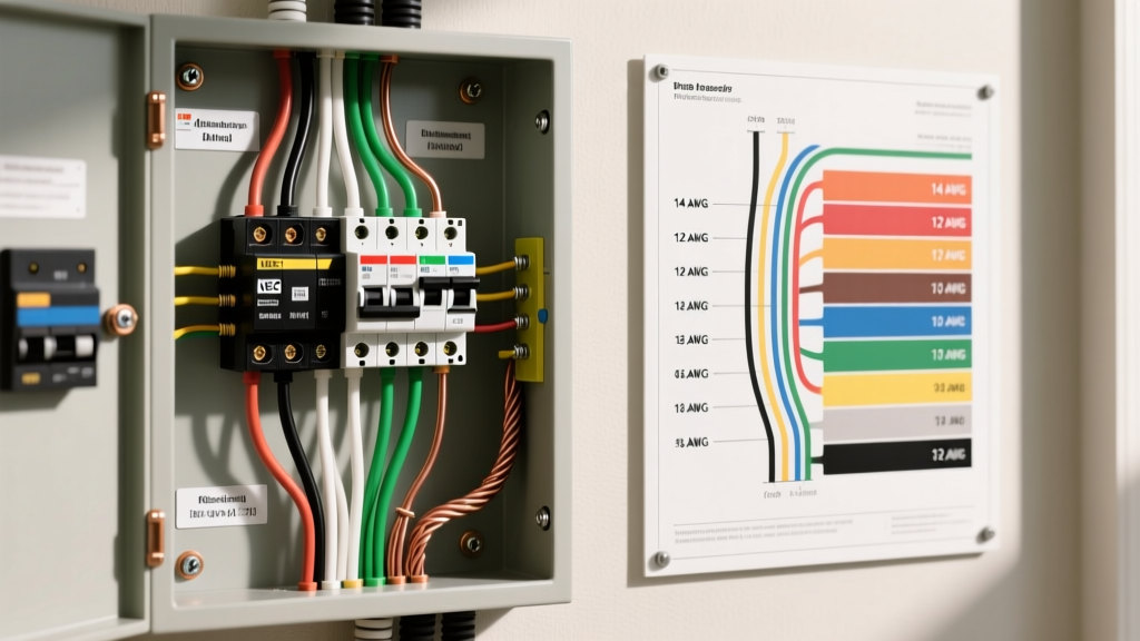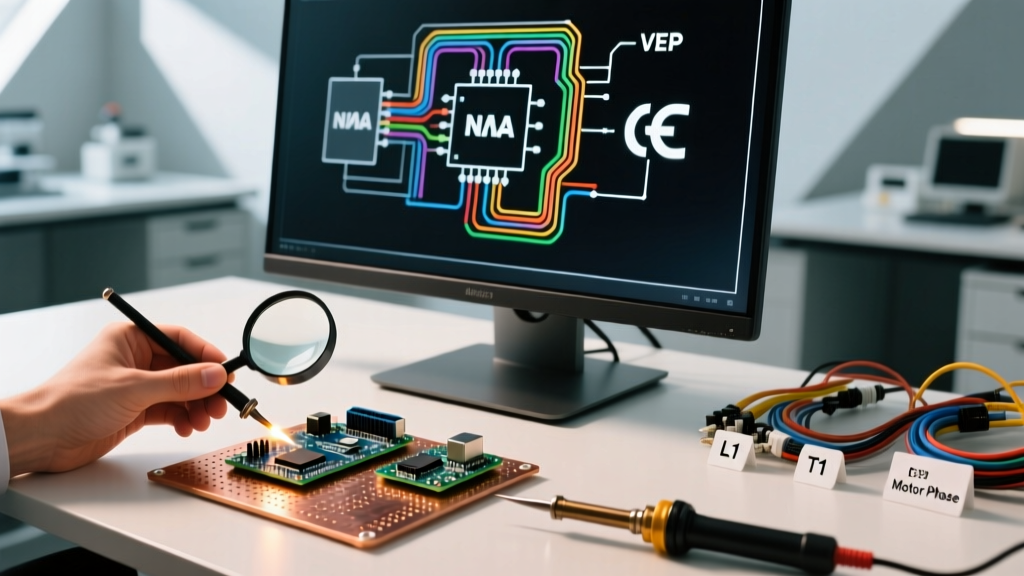

The Shift from Hand-Drawn to Digital Motor Schematics
Designing motor control circuits is an unforgiving discipline. A single misrouted wire in a Star-Delta starter or an incorrectly specified Variable Frequency Drive (VFD) can result in catastrophic equipment failure, arc flash incidents, or costly downtime. Historically, electrical engineers relied on hand-drafted schematics or generic CAD tools, leading to disconnected cross-references and manual Bill of Materials (BOM) errors. Today, specialized electrical wiring schematic software has become the industry standard for motor wiring tutorials and professional panel design.
Unlike vanilla CAD programs, purpose-built electrical design tools utilize relational databases. When you place a motor starter coil (e.g., a Schneider Electric TeSys D-line contactor) on a schematic, the software automatically tracks its auxiliary contacts across multiple pages, updates wire numbering, and generates real-time terminal diagrams. For professionals and advanced DIYers tackling complex 3-phase motor controls, selecting the right software is the first critical step in ensuring safety and NEC compliance.
Core Features to Demand in Motor Wiring Software
When evaluating electrical wiring schematic software specifically for motor applications, generic drawing tools will not suffice. You must look for the following advanced capabilities:
- Dynamic Cross-Referencing: The ability to automatically link a contactor coil on page 3 with its normally open (NO) and normally closed (NC) auxiliary contacts scattered across pages 4 and 5.
- NEMA and IEC Symbol Libraries: Motor schematics vary wildly by region. North American designs typically use NEMA-standard ladder logic symbols, while international projects require IEC 60617 symbols. Top-tier software allows one-click conversion between these standards.
- Automated Wire Numbering: Proper motor wiring requires strict tagging protocols (e.g., L1, L2, L3 for line side; T1, T2, T3 for load side; and sequential numbering for control circuits). The software must auto-number wires based on user-defined potential rules.
- Macro and Circuit Reusability: The ability to save a fully wired Direct-On-Line (DOL) reversing starter circuit as a macro, allowing you to drop it into future projects with a single click, complete with BOM data.
2026 Software Comparison Matrix for Motor Control Design
The landscape of electrical design tools has evolved significantly. Below is a comparative analysis of the leading electrical wiring schematic software platforms available in 2026, specifically evaluated for motor control and panel design workflows.
| Software Platform | Best Application | Est. Pricing (2026) | Motor Library Depth | Learning Curve |
|---|---|---|---|---|
| EPLAN Electric P8 | Large-scale industrial MCCs & PLC integration | $4,500 - $7,000+ | Exceptional (Database-driven) | Steep |
| AutoCAD Electrical | Familiar 2D drafting with electrical toolsets | ~$1,975 / year | High (Extensive manufacturer parts) | Moderate |
| SolidWorks Electrical | 3D panel layout & electromechanical integration | $3,500 - $5,000 | High (3D component models included) | Steep |
| SkyCAD Electrical | Independent contractors & mid-sized panels | $500 - $1,200 | Moderate (Good for standard starters) | Low |
| ProfiCAD | Quick diagrams, DIYers, and basic documentation | Free / $70 (Pro) | Basic (Manual symbol creation often needed) | Very Low |
Note: Pricing reflects estimated commercial licensing costs as of early 2026 and may vary based on regional distributors and maintenance agreements.
Step-by-Step: Designing a VFD Motor Circuit in Schematic Software
To demonstrate the practical application of these tools, let us walk through the workflow of designing a 480VAC 3-phase motor circuit controlled by an ABB ACS580 VFD using a professional electrical wiring schematic software platform like AutoCAD Electrical or EPLAN.
Step 1: Power Supply and Disconnect
Begin by placing the 3-phase power source. Insert a fused disconnect switch (e.g., Eaton 600V Class J fuse block). The software will automatically assign wire tags (L1, L2, L3) and prompt you to define the wire gauge (e.g., 4 AWG THHN for a 60A circuit). The software's electrical rules engine will flag an error if the selected fuse rating exceeds the wire ampacity based on NEC Table 310.16.
Step 2: Line Reactors and VFD Integration
Next, insert a 3% impedance line reactor to mitigate harmonic distortion and protect the VFD from voltage spikes. Wire the reactor output to the ABB ACS580 input terminals (R, S, T). Modern software libraries include manufacturer-specific terminal strips, meaning the BOM will automatically capture the exact ABB part number and necessary DIN rail mounting hardware.
Step 3: Motor Output and Grounding
Route the output from the VFD (U, V, W) to the motor. Crucially, the software must distinguish between power ground (PE) and VFD-specific high-frequency grounding. Use the software's shielded cable macro to specify a symmetrical shielded VFD cable (e.g., Belden 10AWG 3-conductor with shield). The schematic will visually denote the shield grounding at the VFD chassis only, preventing ground loops—a common failure mode in digital schematics designed by novices.
Step 4: Control Circuit and Interlocks
Design the 24VDC control circuit for the VFD start/stop and speed reference. Insert a 3-wire control schematic macro. The software will automatically cross-reference the start pushbutton (NO), stop pushbutton (NC), and the VFD digital input relay. If you add an emergency stop (E-Stop) hardwired to the VFD's Safe Torque Off (STO) terminals, the software will generate a safety matrix report required for modern compliance audits.
Common Failure Modes in Digital Schematics (and How to Avoid Them)
Even with advanced electrical wiring schematic software, user error can lead to dangerous physical implementations. Be vigilant against these specific edge cases:
Expert Warning: Never rely solely on the software's default wire gauge suggestions for motor circuits with high inrush currents. While the software calculates based on Full Load Amps (FLA), it may not account for NEMA Design E motor starting characteristics or voltage drop over long cable runs. Always manually verify voltage drop calculations for runs exceeding 100 feet.
- Missing Interlocks: In reversing motor starters, mechanical and electrical interlocks are mandatory. Software will not automatically insert an electrical interlock (NC contact of the reverse contactor in series with the forward coil) unless you specifically use a verified reversing starter macro. Missing this results in a dead short.
- Overloaded Control Transformers: When designing the control circuit, engineers often forget to sum the inrush VA (Volt-Amps) of all contactor coils sealing in simultaneously. Use the software's load calculation tool to size the control transformer (e.g., 150VA vs 250VA) to prevent voltage sag during motor starting.
- Incorrect NEMA/IEC Sizing: A NEMA Size 2 contactor is not physically or electrically identical to an IEC equivalent, despite similar HP ratings. Always use the software's manufacturer-specific part number lookup to ensure the physical panel layout matches the schematic.
Integrating Standards and Compliance
Professional motor wiring must adhere to rigorous safety and performance standards. When utilizing electrical wiring schematic software, ensure your symbol libraries and design rules are configured to comply with NEMA standards for industrial control equipment, as well as NFPA 70 (NEC) Article 430, which governs motors, motor circuits, and controllers. Advanced software packages allow you to run automated design rule checks (DRC) that flag violations, such as missing motor overload protection or improperly sized branch circuit conductors, before the schematic ever reaches the panel builder.
Expert Verdict: Which Tool Should You Choose?
If you are an independent contractor or advanced DIYer building standard DOL, Star-Delta, or soft-starter panels, SkyCAD Electrical offers the best balance of affordability, intuitive motor macros, and automated BOM generation. For large-scale industrial facilities, OEMs designing complex Motor Control Centers (MCCs), or engineers integrating motor drives with extensive PLC I/O, EPLAN Electric P8 remains the undisputed heavyweight champion in 2026, despite its steep learning curve and premium price tag. Ultimately, investing in dedicated electrical wiring schematic software transforms motor circuit design from a risky, manual drafting exercise into a precise, database-driven engineering process.