
The Anatomy of a Wiring Diagram for Boat Trailer Systems
Designing and maintaining a reliable wiring diagram for boat trailer applications requires a fundamentally different approach than standard utility or RV trailers. Boat trailers face the harshest operational environments of any towed vehicle: repeated submersion in water (often highly corrosive saltwater), extreme thermal shock when hot trailer hubs hit cold lake or ocean water, and constant exposure to road debris. As of 2026, the shift toward fully submersible LED lighting kits has reduced overall amperage draw, but it has also introduced new sensitivities to voltage drop and ground fault resistance.
A proper marine trailer wiring setup must account for galvanic corrosion, voltage drop over long tongue runs, and waterproof termination. According to BoatUS, electrical failure remains the number one cause of roadside trailer breakdowns, with the vast majority stemming from compromised grounds and corroded splices rather than blown bulbs.
Why Standard Automotive Wire Fails on Boat Ramps
The most critical mistake DIYers make when referencing a generic wiring diagram for boat trailer builds is using standard automotive wire (SAE J1128). Automotive wire features untinned copper strands. When exposed to the humid, saline environment of a boat ramp, untinned copper rapidly oxidizes, creating a green, powdery corrosion that increases electrical resistance and causes dim lights or total failure.
The Expert Standard: You must use SAE J378 marine-grade tinned copper wire (such as Ancor Marine Grade wire). The individual copper strands are coated in a micro-layer of tin, which acts as a sacrificial barrier against oxidation, ensuring the wire remains flexible and conductive even if water breaches the outer PVC jacket.
Standard Color Code Matrices (4-Way, 5-Way, and 7-Way)
Understanding the pinout and color code is the foundation of your wiring diagram for boat trailer harnesses. While the 4-way flat is common on small jon boats and kayaks, the 5-way flat is the undisputed industry standard for boat trailers equipped with surge brakes. The 7-way RV blade is typically reserved for large, multi-axle yacht trailers requiring auxiliary power or electric brakes.
| Connector Type | Pin / Function | Wire Color | Marine Application Notes |
|---|---|---|---|
| 4-Way Flat | Ground (Pin 1) | White | Must be bonded to clean, bare metal on the trailer tongue. |
| Tail / Running (Pin 2) | Brown | Powers side markers and tail lights. Use 14 AWG for trailers over 20ft. | |
| Left Turn / Stop (Pin 3) | Yellow | Routes down the driver's side of the trailer. | |
| Right Turn / Stop (Pin 4) | Green | Routes down the passenger side of the trailer. | |
| 5-Way Flat | Ground (Pin 1) | White | Same as 4-way, but requires a heavier gauge (12 AWG) due to solenoid draw. |
| Tail / Running (Pin 2) | Brown | Standard running lights. | |
| Left Turn / Stop (Pin 3) | Yellow | Standard left signal. | |
| Right Turn / Stop (Pin 4) | Green | Standard right signal. | |
| Aux / Reverse (Pin 5) | Blue | CRITICAL: Tied to the tow vehicle's reverse light circuit to trigger the surge brake reverse lockout solenoid. | |
| 7-Way RV Blade | Ground (Pin 1) | White | Heavy-duty ground (10 AWG recommended). |
| 12V Auxiliary (Pin 4) | Black | Used for charging a breakaway battery or powering a winch. | |
| Electric Brakes (Pin 2) | Blue | Rare on boat trailers; used only on large yacht trailers with electric over hydraulic (EOH) brakes. | |
| Tail / Running (Pin 6) | Brown | Standard running lights. | |
| Right Turn (Pin 3) | Green | Standard right signal. | |
| Left Turn (Pin 7) | Red | Note: 7-way RV uses Red for Left, unlike the 4/5-way Yellow. | |
| Reverse / Aux (Pin 5) | Yellow | Used for reverse lockout solenoids on 7-way setups. |
The 5-Way Blue Wire: The Surge Brake Lockout Solenoid
When reviewing a wiring diagram for boat trailer setups with surge brakes, the 5th pin (Blue wire) is often misunderstood. When you shift your tow vehicle into reverse to back down the boat ramp, the tow vehicle's reverse lights send 12V down the Blue wire. This energizes an electromagnetic solenoid on the trailer's surge brake coupler, physically blocking the master cylinder from engaging. If this wire is miswired, corroded, or suffers from voltage drop, your trailer brakes will lock up every time you try to back up the ramp, potentially destroying your tire tread or winch strap.
Wire Gauge Selection: AWG vs. Run Length & Amperage
According to NHTSA FMVSS 108 regulations, trailer lighting must meet specific candela output requirements. If your wire gauge is too thin, voltage drop over the length of the trailer tongue will result in dim lights that fail to meet legal safety standards, even if the bulbs are brand new.
Use this 2026 reference matrix to select the correct tinned copper wire gauge based on your trailer's total harness length (from the tow vehicle plug to the furthest tail light):
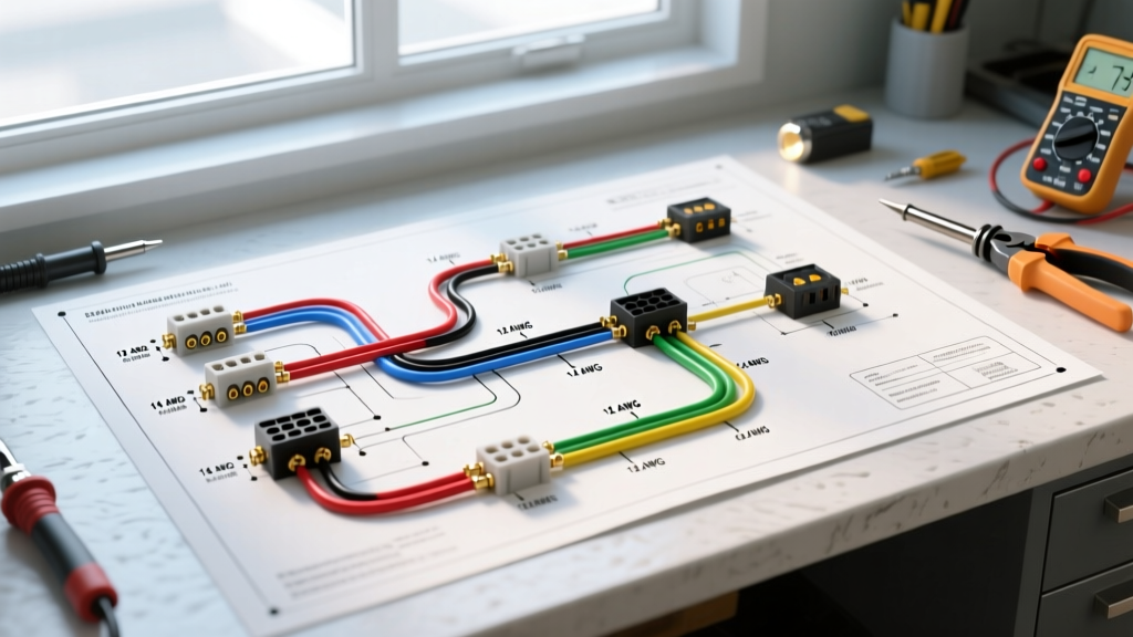
- 16 AWG (Up to 10 Amps / Under 15ft runs): Acceptable only for short, lightweight kayak or PWC trailers utilizing exclusively low-draw LED lighting kits (e.g., Optronics Submersible LEDs drawing <0.2A per lamp).
- 14 AWG (Up to 15 Amps / 15ft to 25ft runs): The minimum recommended standard for the main harness on most single-axle boat trailers. Handles standard incandescent bulbs and long LED runs without noticeable voltage drop.
- 12 AWG (Up to 20 Amps / Over 25ft runs): Required for the main power feed on tandem-axle boats (20ft+ boats) where the tongue alone is 6-8 feet long. Also mandatory for the White ground wire and the Blue reverse lockout circuit to ensure the solenoid receives a full 12V.
- 10 AWG (Up to 30 Amps): Reserved for the 7-Way auxiliary 12V Black wire (charging a breakaway battery) or the main ground wire on heavy-duty tri-axle yacht trailers.
Submersion-Proof Termination Protocol
The most robust wiring diagram for boat trailer harnesses will still fail if the physical connections are compromised. Water wicking through wire capillaries is a silent killer of marine electronics.
- Ditch the Solder: While soldering is great for indoor electronics, standard rosin-core solder can trap moisture and create brittle joints that crack under road vibration. The marine industry standard is a high-pressure mechanical crimp.
- Use Adhesive-Lined Heat Shrink: Standard electrical tape is useless on a boat trailer; it unwraps when submerged in cold water. You must use adhesive-lined (dual-wall) heat shrink tubing, such as 3M MDT or Ancor Marine Heat Shrink. When heated, the inner wall melts and forms a 100% waterproof resin seal around the crimp.
- Dielectric Grease is Mandatory: Apply a liberal amount of silicone dielectric grease (e.g., CRC or Permatex) inside the 4-way or 5-way plug housing and on all bulb sockets before assembly. This displaces oxygen and prevents galvanic corrosion on the brass pins.
Expert Insight: The LED Grounding Paradox
Many DIYers upgrade to LED submersible lights (like the innovative 2026 models from Attwood or Optronics) and are confused when the lights flicker or fail to work, despite the LEDs requiring only a fraction of the amperage of old halogen bulbs. LEDs are highly sensitive to resistance. If your trailer relies on "grounding through the hitch ball" rather than a dedicated White ground wire run all the way back to the tow vehicle's battery negative, the micro-resistance of a rusty hitch ball will cause LED driver boards to shut down. Always run a dedicated, continuous White ground wire.
Advanced Troubleshooting: Submersion Shorts and Thermal Shock
Even with a perfect wiring diagram for boat trailer setups, physical trauma occurs. The most common failure mode specific to boat trailers is thermal shock implosion. When you back a trailer with hot brake drums and hot incandescent light housings into 55°F lake water, the rapid cooling creates a vacuum inside the light housing. If the housing seal is compromised, water is violently sucked into the bulb socket, instantly shorting the circuit and blowing the tow vehicle's fuse.
Troubleshooting Steps:
- Step 1: Check the tow vehicle's fuse panel first. A blown "Trailer Tow" or "Running Light" fuse almost always indicates a submerged short at the rear license plate light or a cracked tail light lens.
- Step 2: Inspect the "wishbone" harness split. The point where the Brown running light wire splits to the left and right sides of the trailer is a high-stress area. Look for cracked PVC insulation exposing tinned copper to the elements.
- Step 3: Test the 5-Way Blue wire with a multimeter. With the tow vehicle in reverse (engine running, parking brake set), you should read 12.5V to 13.2V at the trailer plug's Blue pin. If you read under 11V, you have a voltage drop issue caused by a corroded splice or an undersized gauge wire feeding the reverse lockout solenoid.
For comprehensive, vehicle-specific plug-and-play adapters and further diagnostic flowcharts, the etrailer wiring FAQ database remains an invaluable companion resource to this guide. By adhering to marine-grade materials, strict gauge sizing, and waterproof termination protocols, your boat trailer lighting system will survive decades of ramp launches without a single electrical fault.