
Introduction to GM HEI Ignition Systems
The General Motors High Energy Ignition (HEI) system, introduced in 1974, revolutionized automotive spark delivery by replacing mechanical breaker points with a solid-state magnetic pickup and an electronic control module. For restorers, hot rod builders, and engine swappers, understanding the exact wiring diagram for GM HEI distributor setups is critical. A miswired HEI system will result in weak spark, premature module failure, or a complete no-start condition. This step-by-step walkthrough covers the industry-standard 4-pin module, high-current relay upgrades, and precise diagnostic measurements to ensure your ignition system performs flawlessly in 2026 and beyond.
Core HEI Components & Current Pricing
Before cutting and crimping wires, verify you have the correct components. The aftermarket is flooded with cheap, offshore modules that fail under high-rpm dwell demands. Stick to OEM or premium aftermarket specifications.
| Component | Part Number / Example | Specs / Notes | Approx. Price (2026) |
|---|---|---|---|
| Standard 4-Pin Module | ACDelco D1361H | OEM replacement, handles up to 6,000 RPM | $35 - $45 |
| Premium Billet HEI | MSD 8365 (Holley) | CNC machined, adjustable advance, high-rpm | $280 - $320 |
| Coil-in-Cap Assembly | ACDelco 336-3906 | Primary: 0.5Ω, Secondary: 8k-10kΩ | $45 - $60 |
| Ignition Wire Set | Taylor 8mm Spiro-Pro | Spiral core, suppresses EMI for EFI swaps | $65 - $85 |
| Automotive Relay (Upgrade) | Bosch 0332014150 | 12V 30A SPST, for dedicated power feed | $10 - $15 |
The Golden Rule: Unswitched vs. Switched 12V Power
Critical Warning: Never wire a GM HEI distributor to the original 'points' ignition wire found on pre-1974 vehicles without modifying the circuit. Points systems utilize a resistance wire that drops voltage to 7V-9V during the 'Run' cycle to prevent coil burnout. HEI modules require a solid, unresisted 12V-14V in both 'Start' and 'Run' positions. Feeding an HEI module with 9V will cause severe spark degradation at high RPM and rapid thermal failure of the internal switching transistor.
According to guidelines published by SAE International regarding automotive electrical loads, ignition systems must maintain voltage within 5% of the alternator's regulated output to ensure proper coil saturation time. If your voltage drops below 11.5V at the BAT terminal, dwell angle shrinks, and misfires occur.
Step-by-Step Wiring Walkthrough: 4-Pin HEI Module
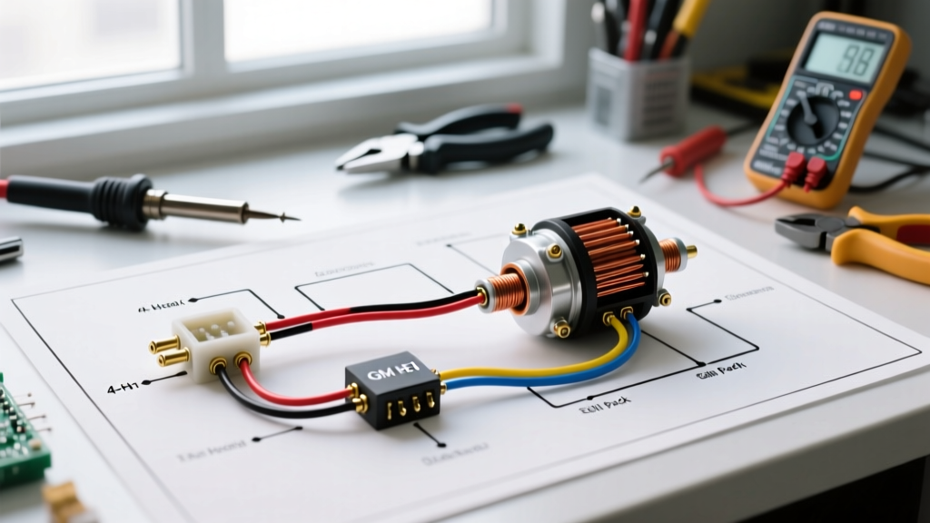
The 4-pin HEI module is the standard for carbureted, non-computer-controlled V8 and V6 engines. The wiring harness consists of only two external connections on the distributor cap: the BAT terminal and the TACH terminal.
Step 1: Sourcing the Correct 12V Ignition Feed
Locate a true 12V ignition-switched source on your fuse block. This terminal must have power when the key is in the 'ON' (Run) and 'START' (Crank) positions. Do not use an accessory (ACC) terminal, as it loses power during cranking, which will kill the engine the moment you release the key from the start position.
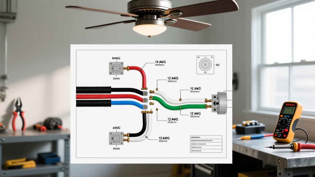
- Wire Gauge: Use a minimum of 12 AWG stranded copper wire (e.g., TXL or GXL cross-linked polyethylene insulation for engine bay heat resistance).
- Protection: Install an inline 15A AGC glass fuse or a 15A mini-circuit breaker within 6 inches of the power source.
- Termination: Crimp a female spade connector with a locking tang to the end of the wire and push it securely onto the 'BAT' terminal on the HEI cap.
Step 2: Wiring the Tachometer Output
The 'TACH' terminal on the HEI cap provides a 12V square-wave pulse that triggers aftermarket tachometers. Never ground this terminal. Grounding the TACH terminal effectively shorts the primary side of the ignition coil to ground while the module is off, which will instantly destroy the HEI module's internal switching transistor. If you are not running a tachometer, simply leave the TACH terminal empty and cover it with a rubber dust boot to prevent corrosion.
Step 3: Grounding the Distributor Housing
The HEI module completes its internal circuit by grounding through the distributor body, into the engine block, and back to the battery. Ensure the distributor mounting flange is free of paint, powder coat, or heavy rust. Furthermore, verify that your engine block is grounded to the chassis and battery negative terminal using a minimum of 2/0 AWG welding cable. A poor engine ground will force the HEI module to seek a ground path through the throttle linkage or steering column, resulting in erratic spark and melted linkage components.
Pro-Tip: The High-Current Relay Upgrade
For high-performance builds or vehicles with long wiring runs (like rear-engine swaps or classic trucks with degraded firewall bulkheads), voltage drop across the ignition switch and firewall connectors is a common failure point. To guarantee 14.2V at the HEI cap, wire a dedicated relay circuit:
- Run a heavy 10 AWG wire directly from the battery positive terminal to pin 30 on a standard Bosch-style 30A relay.
- Install a 20A inline fuse on this 10 AWG feed.
- Wire the original, low-current ignition switch 'RUN' wire to pin 86 (relay coil trigger).
- Ground pin 85 (relay coil ground) to the chassis.
- Run a new 12 AWG wire from pin 87 (relay output) directly to the HEI BAT terminal.
This setup uses the ignition switch only to trigger the relay's low-amp electromagnetic coil, while the heavy current required for coil saturation (up to 8 amps during extended dwell) flows directly from the battery through the relay contacts.
Coil-in-Cap vs. Remote Coil Wiring Matrix
Depending on your engine bay clearance (e.g., tall deck V8s, blower setups, or marine applications), you may need to run a remote coil. Here is how the wiring shifts between the two configurations.
| Feature | Coil-in-Cap (Standard) | Remote Coil (External) |
|---|---|---|
| Coil Location | Integrated into the distributor cap | Mounted to firewall or valve cover |
| Primary Wiring | Internal metal tabs press against module | Requires adapter harness from cap to external coil (+ and -) |
| Secondary (High Voltage) | Direct contact with rotor button | Standard coil wire from external tower to center cap tower |
| Heat Dissipation | Poor (trapped under cap, causes ozone buildup) | Excellent (exposed to ambient airflow) |
| Best Application | Stock restorations, standard street builds | Supercharged engines, marine, tight hood clearance |
Understanding 5-Pin and 7-Pin Computer-Controlled Modules
If you are wiring a mid-1980s GM vehicle equipped with Computer Command Control (CCC), you will encounter a 5-pin or 7-pin HEI module. The additional pins interface directly with the Engine Control Module (ECM). The 5th pin is typically an ESC (Electronic Spark Control) or timing advance retard wire. Crucial Edge Case: If you install a 5-pin module into a pre-computer carbureted engine and leave the 5th pin unconnected, the module will default to a retarded base timing state, causing severe power loss and overheating. You must ground the 5th pin to the distributor base to force the module into full advance mode when bypassing the ECM.
Diagnostics: Multimeter Testing & Failure Modes
When troubleshooting a no-spark condition, do not immediately replace the module. Follow the diagnostic protocols recommended by safety and engineering bodies like the National Fire Protection Association (NFPA) to prevent electrical fires and component damage. Use a digital multimeter (DMM) to isolate the fault.
| Symptom | Probable Cause | Multimeter Test / Fix |
|---|---|---|
| Dead No-Spark (Cranking) | Loss of 12V BAT feed or blown fuse | Test BAT terminal with DMM. Must read >11.5V during crank. |
| Engine dies when hot, restarts when cold | Thermal failure of HEI module transistor | Swap with known good ACDelco D1361H module. Apply thermal paste to module base. |
| Weak spark, backfires through carb | Cracked pickup coil or broken magnet | Test pickup coil leads (unplugged). Resistance must be 500Ω - 1500Ω. |
| Tachometer reads 0 or pegs max | TACH terminal shorted or wired to 12V source | Verify TACH wire goes ONLY to tach signal input. Never to 12V or Ground. |
| High RPM misfire (above 5,000 RPM) | Voltage drop at BAT terminal or weak coil | Test primary coil resistance. Should be ~0.5Ω. Upgrade to relay feed. |
Final Verification and Safety Checks
Before cranking the engine, double-check all crimp connections. As noted in the ACDelco OEM Parts Catalog technical bulletins, the HEI module's ground path relies heavily on the physical mating surface between the module and the distributor housing. Always apply a thin, even layer of dielectric thermal compound (not standard grease) to the back of the module before bolting it down. This compound transfers heat away from the silicon switching transistor into the aluminum housing, drastically extending the lifespan of your ignition system. Ensure all spark plug wires are routed away from exhaust headers to prevent melting and cross-firing, securing them with loom brackets and zip ties. With the power routed correctly and the grounds verified, your GM HEI distributor will deliver a massive 40,000-volt spark for reliable, maintenance-free ignition.