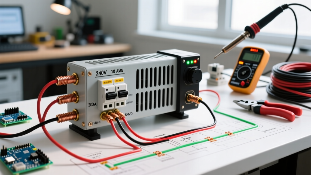

Understanding the 240V Electric Heater Wiring Diagram
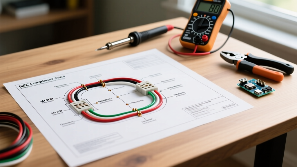
Wiring a high-capacity 240V electric space heater requires strict adherence to the National Electrical Code (NEC) and a clear understanding of line-voltage circuitry. Unlike standard 120V plug-in appliances, hardwired 240V heaters—such as the industry-standard Fahrenheat FUH54 (5000W) garage heater—demand a dedicated double-pole breaker, specific wire gauges, and a line-voltage thermostat. This comprehensive guide breaks down the exact electric heater wiring diagram and provides a step-by-step walkthrough for a safe, code-compliant installation.
According to NFPA 70 (NEC) Article 424, which governs Fixed Electric Space-Heating Equipment, all continuous heating loads must be calculated at 125% of their rated amperage. A 5000W heater operating at 240V draws 20.83 amps. Multiplying this by 1.25 yields 26.04 amps, dictating the absolute necessity of a 30-amp double-pole breaker and 10 AWG copper conductors.
Pre-Installation: Load Calculation & Material Sizing
Before pulling any wire, you must gather the correct materials. Using undersized wire or a single-pole breaker for a 240V load is a severe fire hazard and an immediate code violation. Below is the exact bill of materials (BOM) and sizing matrix for standard residential 240V electric heaters.
| Heater Wattage (240V) | Base Amperage | Continuous Load (125%) | Required Breaker | Min. Wire Gauge (Copper) |
|---|---|---|---|---|
| 2000W | 8.3A | 10.4A | 15A Double-Pole | 14 AWG (12 AWG recommended) |
| 3000W | 12.5A | 15.6A | 20A Double-Pole | 12 AWG |
| 4000W | 16.6A | 20.8A | 25A or 30A Double-Pole | 10 AWG |
| 5000W (e.g., FUH54) | 20.8A | 26.0A | 30A Double-Pole | 10 AWG |
| 7500W | 31.2A | 39.0A | 40A Double-Pole | 8 AWG |
Required Tools & Components
- Circuit Breaker: Square D HOM230 (30A, 2-pole, 120/240V) or equivalent for your panel brand.
- Cable: Southwire 10/2 NM-B (Non-Metallic Sheathed) with ground. The white neutral wire will be re-identified as a hot leg.
- Thermostat: Honeywell Home CT410B (Double-pole, line-voltage, 22A max). Never use a single-pole thermostat for a 240V heater; it leaves 120V energized at the unit even when turned off.
- Tools: Wire strippers calibrated for 10 AWG, torque screwdriver, non-contact voltage tester, and a digital multimeter.
Step-by-Step Wiring Walkthrough
Step 1: Main Panel Breaker Installation
Shut off the main breaker to de-energize the panel. Verify zero voltage at the bus bars using a CAT III or CAT IV multimeter. Install the 30A double-pole breaker into two adjacent, available slots on the panel bus bar. Because this is a 240V circuit, no neutral wire is connected to the panel's neutral bar. Connect the bare copper ground wire from your 10/2 NM-B cable to the panel's equipment grounding bar. Torque the ground lug to the manufacturer's specification (typically 12-14 in-lbs for 10 AWG).
Step 2: Routing the 10/2 NM-B Cable
Run the 10/2 NM-B cable from the main panel to the thermostat location, and then from the thermostat to the heater's junction box. Per NEC Article 300.4, protect the cable from physical damage. If running through exposed garage studs, ensure the cable is set back at least 1.25 inches from the face of the stud, or install nail plates. Maintain a minimum bend radius of 1.5 inches to prevent damaging the internal paper separator and insulation.
Pro-Tip: At the thermostat box, leave at least 8 inches of slack. At the heater junction box, leave 6 inches of slack. Strip the outer NM-B jacket exactly 1/4 inch past where it enters the cable clamp to prevent the clamp from biting into the individual wire insulation.
Step 3: Wiring the Line-Voltage Thermostat
The thermostat acts as the switching mechanism for both hot legs. Using the Honeywell CT410B as our reference model:
- Line Side (From Panel): Connect the black wire from the panel to the L1 terminal. Take the white wire from the panel, wrap it with black electrical tape (or red PhaseTape) at both ends to re-identify it as a hot conductor, and connect it to the L2 terminal.
- Load Side (To Heater): Connect the black wire heading to the heater to the T1 terminal. Connect the re-identified white wire heading to the heater to the T2 terminal.
- Grounding: Splice all bare copper ground wires together using a red or gray wire nut (rated for 3x 10 AWG) and attach a 10 AWG pigtail to the metal thermostat junction box grounding screw. The thermostat itself does not require a ground connection on its terminals, but the metal box must be grounded.
Step 4: Terminating the Heater Junction Box
Open the Fahrenheat FUH54 junction box. You will find two factory-installed heating element leads (usually black and red, or two blacks) and a green grounding screw.
- Connect the black load wire from the thermostat to one of the heater's element leads using a heavy-duty wire nut or a WAGO 221-612 lever connector.
- Connect the re-identified white load wire to the second heater element lead. (Polarity does not matter on the heating elements).
- Terminate the bare ground wire directly to the heater chassis grounding screw. Torque to 14 in-lbs to ensure a low-impedance fault path.
Secure the junction box cover, mount the heater to the ceiling or wall bracket ensuring at least 3 inches of clearance from combustible materials, and restore power at the main panel.
Edge Cases & Troubleshooting Common Failures
Even with a perfect electric heater wiring diagram, field conditions can introduce variables. The U.S. Department of Energy notes that improper installation accounts for the vast majority of electric heating inefficiencies and failures. Here is how to troubleshoot the most common edge cases:
The Breaker Trips Immediately Upon Energizing
Failure Mode: A dead short in the circuit. This usually occurs if the bare ground wire is touching one of the hot terminals inside the heater junction box, or if the NM-B cable was stapled too tightly, crushing the insulation and causing the black and white wires to arc.
Resolution: Disconnect power. Use a multimeter in continuity mode to test between L1 and Ground, and L2 and Ground at the panel. If continuity exists, trace the physical route of the cable to find the crush point or inspect the heater junction box for stray ground strands.
The Heater Runs, but the Thermostat Clicks Constantly
Failure Mode: Thermostat placement error. If the thermostat is mounted directly in the heater's discharge airflow path, or on an exterior wall without an insulation backplate, it will satisfy the setpoint in seconds, shut off, cool rapidly, and call for heat again. This rapid cycling destroys the thermostat's bimetallic switch and the heater's contactor.
Resolution: Relocate the thermostat to an interior wall, approximately 5 feet above the floor, away from direct draft paths. Install a foam insulation gasket behind the thermostat baseplate to prevent cold wall drafts from falsifying the ambient temperature reading.
Heater Blows Cold Air
Failure Mode: One of the two 240V hot legs is dead, or the internal thermal limit switch has tripped. If only 120V is reaching the unit (e.g., one breaker pole failed or a wire nut melted off L2), the heater's internal fan will run, but the elements will not energize due to the voltage drop.
Resolution: Test the voltage at the heater's wire nuts with the circuit energized. You must read exactly 240V across the two hot wires, and 120V from each hot wire to ground. If you read 120V across the two hots, a hot leg is lost. Check the breaker and all thermostat terminal torques. If voltage is correct, press the manual reset button on the heater's internal thermal limit disc (usually located behind the front grill).
Safety Warning: Working inside a main electrical panel exposes you to lethal voltage, even when the main breaker is off, as the service entrance conductors remain live. As highlighted by OSHA's electrical safety guidelines, always use appropriately rated PPE, insulated tools, and verify zero energy before touching any bus bar or terminal. If you are not confident in your ability to safely terminate a 240V circuit, hire a licensed electrical contractor.
Final Inspection & Commissioning
Once the physical wiring is complete, commission the system. Turn the thermostat to its maximum setting. The Fahrenheat FUH54 features an internal fan delay; the heating elements will energize first, and the fan will not start until the internal plenum reaches approximately 120°F to prevent blowing cold air. This delay can take up to 45 seconds. Once the fan engages, use an infrared thermometer to verify the discharge air temperature, which should be roughly 40°F to 50°F above the ambient room temperature. Properly executed, this 240V electric heater wiring diagram will provide decades of safe, efficient, and code-compliant heating for your workspace.