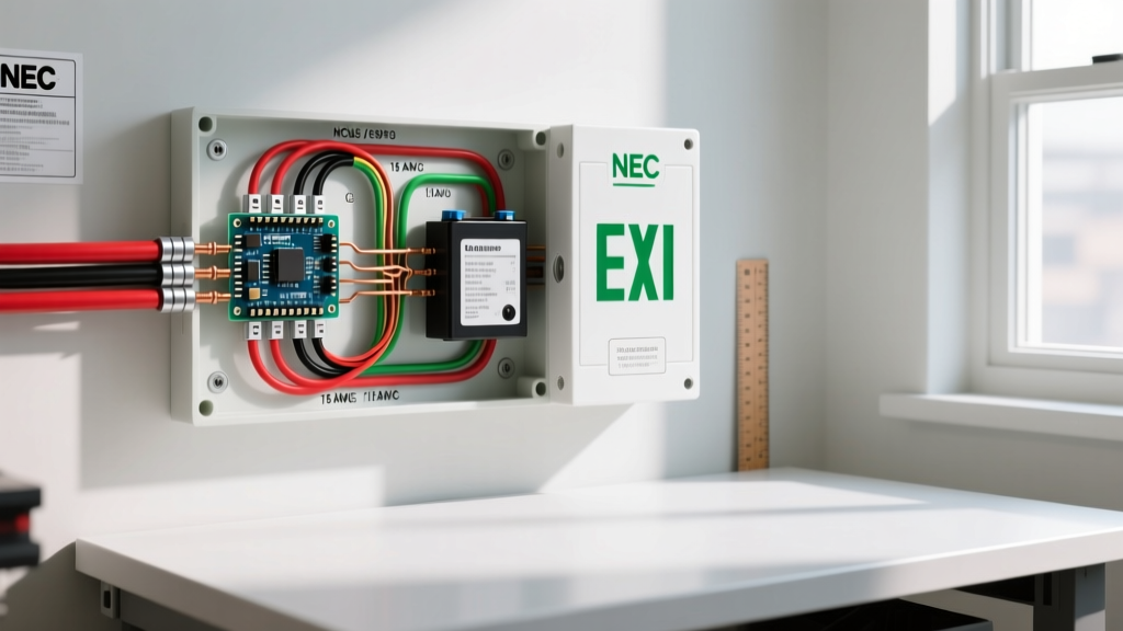

The Critical Role of Hardwired Exit Sign Wiring
When it comes to commercial and multi-family residential life safety systems, the wiring diagram for exit sign fixtures is not just a matter of illumination—it is a strict legal and safety mandate. Modern LED exit signs with battery backups, such as the widely deployed Lithonia Lighting LQM series or Hubbell Premise Wiring models, operate as self-contained emergency appliances. They require precise hardwiring to ensure seamless transition from utility power to internal battery reserves during a grid failure.
Unlike standard lighting appliances, exit signs are governed by rigorous electrical codes. A miswired transfer relay or an improperly grounded chassis can result in a fixture that fails to illuminate during a fire or blackout, leading to severe liability and failed municipal inspections. This comprehensive tutorial breaks down the exact wiring schematic, installation procedures, and National Electrical Code (NEC) requirements for hardwiring emergency exit signs in 2026.
Anatomy of an LED Exit Sign with Emergency Backup
Before connecting any wires, it is essential to understand the internal architecture of the fixture. A standard combination exit sign and emergency light contains four primary electrical subsystems:
- LED Driver Board: Steps down 120V/277V AC to the low-voltage DC required by the LED array (typically 2V to 4V DC).
- Solid-State Transfer Relay: The brain of the operation. It constantly monitors the AC line voltage. If voltage drops below 80% of nominal, the relay trips, disconnecting the LEDs from the AC driver and routing power from the battery.
- Battery Charger Circuit: A micro-processor-controlled charging module that maintains the internal battery (NiCad, NiMH, or LiFePO4) at full capacity without overcharging.
- Push-to-Test Switch: A mechanical or solid-state switch that simulates a power failure by temporarily severing the AC line to the LEDs, forcing the battery to engage.
Standard Wiring Diagram for Exit Sign Connections
Because physical schematics vary slightly by manufacturer, we will outline the universal 120V AC wiring diagram for exit sign installations. Most commercial fixtures utilize a standard 3-wire or 4-wire whip (pigtail) or internal terminal block.
Terminal Block Color Coding & Mapping
| Wire Color | Function | Connection Point | NEC Designation |
|---|---|---|---|
| Black | Unswitched Hot (Line 1) | Connects to the main AC driver and battery charger. | Ungrounded Conductor |
| White | Neutral | Completes the 120V AC circuit for the driver/charger. | Grounded Conductor |
| Green / Bare | Equipment Ground | Must bond to the metal junction box and fixture chassis. | Equipment Grounding Conductor |
| Red (or Switched Black) | Switched Hot (Line 2) | Connects to a wall switch or fire alarm relay for manual/remote testing. | Switched Ungrounded Conductor |
Expert Note: If your installation does not utilize a remote test switch or fire alarm panel integration, the Red (Switched Hot) wire must be capped off with a wire nut and tucked into the junction box. Never connect the Red wire directly to the unswitched Black wire, as this will bypass the internal test circuitry and may damage the solid-state relay.
Step-by-Step Appliance Wiring Tutorial
Follow this precise procedure to ensure a safe, code-compliant installation. This guide assumes a standard 120V AC, 15-amp or 20-amp branch circuit.
Step 1: Circuit Verification and Prep
Turn off the breaker and verify zero voltage using a CAT III non-contact voltage tester and a digital multimeter. Exit signs are often wired to dedicated emergency circuits or standard lighting circuits. If wired to a standard lighting circuit, ensure the circuit is not controlled by a standard occupancy sensor, as the exit sign must remain powered 24/7 to charge the battery.
Step 2: Wire Stripping and Preparation
For 14 AWG or 12 AWG solid THHN/THWN copper wire, strip exactly 5/8 inch (16mm) of insulation. Stripping too little will result in the terminal screw biting into the insulation, causing a high-resistance connection and eventual thermal failure. Stripping too much exposes bare copper, creating a shock hazard inside the cramped fixture canopy.
Step 3: Making the Connections
- Ground First: Connect the Green/Bare wire to the junction box ground screw and the fixture's green ground pigtail. Torque to 5-7 in-lbs.
- Neutral: Connect the White fixture wire to the White branch circuit wire using a UL-listed wire connector (e.g., Ideal Wire-Nut or Wago 221 lever nut).
- Unswitched Hot: Connect the Black fixture wire to the Black (constant hot) branch circuit wire.
- Switched Hot (Optional): Connect the Red fixture wire to the switched leg returning from your test switch or fire alarm relay.
Step 4: Voltage Drop Considerations for Long Runs
In large commercial corridors, the distance from the electrical panel to the last exit sign can exceed 150 feet. While LED exit signs draw minimal current (typically under 0.05 amps), the internal battery charger requires a stable voltage to initiate the bulk-charge phase. If voltage drop exceeds 3%, the charger may fail to recognize a depleted battery. For runs exceeding 100 feet on a 120V circuit, upsize your wiring from 14 AWG to 12 AWG to maintain voltage integrity.
Battery Backup Technologies: NiCad vs. LiFePO4
The internal battery is the most critical component of the exit sign appliance. In 2026, the industry has largely shifted away from older chemistries, but you will still encounter them in retrofit scenarios.
| Feature | NiCad (Nickel-Cadmium) | NiMH (Nickel-Metal Hydride) | LiFePO4 (Lithium Iron Phosphate) |
|---|---|---|---|
| Lifespan | 3 to 5 years | 5 to 7 years | 10+ years |
| Memory Effect | High (Requires full discharge cycles) | Low | None |
| Operating Temp | -20°C to 50°C | 0°C to 45°C | -20°C to 60°C |
| Cost (Replacement) | $12 - $18 | $20 - $28 | $35 - $55 |
| Environmental | Contains toxic Cadmium (Hazmat) | RoHS Compliant | RoHS Compliant, Non-toxic |
2026 Recommendation: Always specify LiFePO4 battery packs for new installations. While the upfront cost of the fixture is roughly $15 to $25 higher, the 10-year lifespan eliminates the labor cost of mid-cycle battery replacements, which typically run $85 to $125 per fixture when factoring in technician time and lift rentals for high-ceiling applications.
NEC & OSHA Compliance Mandates
Wiring an exit sign correctly is only half the battle; the installation must comply with federal and local life safety codes. According to the NFPA 70 National Electrical Code, specifically Article 700 (Emergency Systems), all emergency illumination and exit signs must provide a minimum of 90 minutes of illumination upon loss of normal power.
Furthermore, Article 700.12 dictates that the battery backup must be capable of delivering the required voltage for the full 90-minute duration without dropping below the LED driver's minimum operating threshold. From an operational standpoint, the OSHA 1910.37 standard mandates that exit routes must be adequately lighted at all times, and exit signs must be illuminated to a minimum of 5 foot-candles on the surface.
Testing and Maintenance Requirements
- 30-Day Test: A 30-second manual test via the push-to-test switch or automated self-diagnostic relay to ensure the transfer mechanism engages.
- Annual Test: A full 90-minute discharge test. Modern self-testing models (e.g., Lithonia ELB series with integrated diagnostics) will log this data and indicate pass/fail via a tricolor LED indicator on the chassis.
Troubleshooting Common Wiring and Component Failures
Even with a perfect wiring diagram for exit sign execution, components degrade. Here is how to diagnose the most common field failures:
1. Fixture Flickers When on Battery Power
Diagnosis: This is rarely a wiring issue and almost always a failing battery or a degraded LED driver capacitor. In NiCad batteries, 'memory effect' or cell shorting causes the voltage to sag under load, causing the LED driver to rapidly cycle on and off. Solution: Replace the battery pack. If flickering persists with a new LiFePO4 pack, the internal transfer relay contacts are pitted and the entire fixture must be replaced.
2. Fixture Does Not Illuminate on AC Power, But Works on Battery
Diagnosis: The unswitched hot (Black wire) has lost continuity, or the internal AC fuse (usually a 1-amp glass fuse on the driver board) has blown due to a transient voltage spike. Solution: Check for 120V at the wire nuts using a multimeter. If voltage is present, open the driver compartment and test the board fuse for continuity.
3. Push-to-Test Switch Fails to Engage Battery
Diagnosis: If the fixture is wired using the 4-wire method, the Switched Hot (Red wire) may have been incorrectly capped or disconnected at the wall switch. The test switch on the wall physically breaks the AC circuit to the Red wire to simulate a blackout. Solution: Verify the wall switch is correctly interrupting the Red wire leg, not the main Black leg.
Final Thoughts on Life Safety Wiring
Treating an exit sign as a standard lighting appliance is a critical error. By strictly adhering to the standard wiring diagram for exit sign fixtures, respecting wire strip lengths, utilizing proper torque on terminal screws, and understanding the nuances of modern LiFePO4 battery chemistry, you ensure that your installation will pass municipal inspections and, more importantly, protect building occupants during an emergency. Always consult the manufacturer's specific wiring addendum included in the carton, as proprietary self-testing diagnostic modules may require an additional low-voltage communication wire for centralized fire panel monitoring.