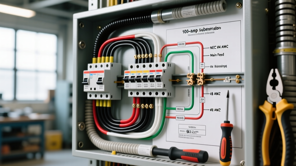

The 2026 Landscape: Why 100 Amp Subpanels are Critical
As residential electrical demands surge in 2026—driven by Level 2 EV chargers, all-electric HVAC systems, and Accessory Dwelling Units (ADUs)—the 100 amp subpanel has become the backbone of modern home expansions. However, reviewing a standard wiring diagram for a 100 amp subpanel reveals a complex web of National Electrical Code (NEC) requirements that, if ignored, can lead to catastrophic neutral-to-ground fault currents, equipment failure, or electrical fires.
This guide bypasses generic DIY advice and dives deep into the exact NEC articles, conductor sizing mathematics, and torque specifications required to install a 100 amp subpanel safely and legally. According to the National Fire Protection Association (NFPA), improper subpanel bonding and undersized feeder conductors remain among the top cited violations by electrical inspectors nationwide.
The Golden Rule: Neutral and Ground Isolation
The most critical safety distinction in any subpanel wiring diagram is the separation of the neutral and ground buses. In your main service panel, the neutral and ground are bonded together (and tied to the earth ground rod). In a subpanel, they must remain completely isolated.
NEC Article 250.142: Use of Grounded Circuit Conductor for Grounding Equipment
The NEC strictly prohibits using the neutral (grounded conductor) as a grounding path for equipment on the load side of the service disconnect. If you leave the green bonding screw or bonding strap installed in a subpanel, any return current on the neutral wire will also travel along the bare copper ground wires. This energizes the chassis of your appliances, creating a severe shock hazard and causing ground-fault circuit interrupters (GFCIs) to trip unpredictably.
Inspector's Note: Before closing the panel cover, physically verify that the green bonding screw has been removed and that the neutral bus bar is floating (isolated from the metal panel enclosure). Most modern subpanels, like the Square D QO or Eaton BR series, ship with the bonding screw uninstalled in a separate bag, but older stock or reused panels require manual verification.
Conductor Sizing: Selecting the Right Feeder Wires
A common and dangerous mistake is sizing wires based on the 90°C column of NEC Table 310.16. While THHN wire is rated for 90°C, the termination lugs on standard 100A breakers and subpanels are only rated for 75°C. Therefore, you must size your conductors using the 75°C column.
Feeder Conductor & Equipment Grounding Conductor (EGC) Chart
| Conductor Type | Copper Size (75°C) | Aluminum Size (75°C) | Max Ampacity | 2026 Avg. Cost per Foot (SER Cable) |
|---|---|---|---|---|
| Hot / Neutral (Current Carrying) | #1 AWG | #1/0 AWG | 100 Amps | $2.85 - $3.40 (Al) / $6.50+ (Cu) |
| Equipment Ground (EGC) | #8 AWG | #6 AWG | N/A (Fault Path) | Included in 4-wire SER |
Note: Sizing the EGC is dictated by NEC Table 250.122, which bases the ground wire size on the rating of the overcurrent device (the 100A breaker), not the ampacity of the hot conductors.
Step-by-Step Feeder Routing and Termination
When executing the wiring diagram for a 100 amp subpanel, the physical termination of the wires is where most heat-related failures occur. Loose connections cause arcing, which melts insulation and starts fires inside the wall cavity.
- Strip the Insulation Precisely: Use a calibrated wire stripper to remove exactly the amount of insulation required by the lug barrel. Exposed copper outside the lug is a shock hazard; insulation inside the lug creates a high-resistance connection.
- Insert and Align: Ensure all strands of the aluminum or copper wire are twisted tightly and inserted fully into the lug barrel. No stray strands should be visible.
- Apply Manufacturer-Specified Torque: This is non-negotiable in modern code enforcement. For a standard Square D 100A main lug or breaker terminating #1/0 AWG aluminum, the required torque is typically 225 inch-pounds (in-lbs).
- Use a Calibrated Torque Tool: Do not guess with a standard screwdriver. Use an inch-pound torque screwdriver (such as the Wiha 60446 or CDI Torque 1002TQIN) to achieve the exact spec printed on the panel label.
The Electrical Safety Foundation International (ESFI) heavily advocates for the use of torque tools in residential installations, noting that aluminum conductors are particularly susceptible to thermal expansion and contraction, which will loosen under-torqued lugs over a 12-to-18-month period.
Top 3 NEC Code Violations in Subpanel Installations
1. Using a 3-Wire Feeder for New Installations
Prior to the 2008 NEC, 3-wire feeders (two hots and a neutral, with the ground bonded to the neutral at the subpanel) were permitted for detached structures. This is now strictly banned for all new installations. You must run a 4-wire feeder (two hots, one neutral, one dedicated ground) to every subpanel, regardless of whether it is in an attached garage or a detached ADU.
2. Undersizing the Grounding Electrode Conductor (GEC)
If your subpanel is in a detached structure, NEC Article 250.32 requires a local grounding electrode system (like two 8-foot copper ground rods). The wire connecting the subpanel's ground bus to these rods (the GEC) must be sized per NEC Table 250.66. For a #1/0 AWG aluminum feeder, you must use a minimum #6 AWG bare copper wire to the ground rods. Using #8 or #10 AWG here is a frequent failure point during inspections.
3. Failing to Provide an Exterior Disconnect (NEC 230.71)
Adopted widely by 2026, the NEC requires an exterior emergency disconnect for one- and two-family dwellings. If your 100A subpanel is fed directly from the main service and acts as a feeder to a detached structure, ensure the feeder originates from a breaker that complies with local exterior disconnect mandates, or install a dedicated 100A disconnect switch on the exterior wall before the feed enters the subpanel.
Frequently Asked Questions (FAQ)
Can I use #2 AWG Aluminum wire for a 100 Amp subpanel?
No. #2 AWG Aluminum is only rated for 90 Amps in the 75°C column (NEC Table 310.16). While some older mobile home standards allowed #2 AWG for 100A services under specific exceptions, standard residential and commercial subpanels require a minimum of #1/0 AWG Aluminum to safely carry 100 Amps without overheating the breaker lugs.
Do I need to apply antioxidant paste to aluminum feeder wires?
Yes. Aluminum oxidizes rapidly when exposed to air, creating a highly resistive layer that generates heat. Apply a UL-listed antioxidant compound (such as Noalox or Ideal Noalox) to the stripped ends of the aluminum conductors before inserting them into the lugs. This is a best practice heavily recommended by the Occupational Safety and Health Administration (OSHA) and major panel manufacturers to prevent lug degradation.
What is the maximum voltage drop allowed for a 100A subpanel feeder?
The NEC recommends (but does not strictly mandate as a hard rejection criteria in all jurisdictions) a maximum voltage drop of 3% for feeders and 5% total from the service to the furthest outlet (NEC Informational Note 210.19). For a 100A subpanel located more than 150 feet from the main panel, you will likely need to upsize your conductors to #2/0 AWG Aluminum or #1/0 AWG Copper to maintain voltage stability for sensitive 2026 smart-home equipment and EV chargers.
Final Safety Verification
Before energizing the panel, perform a continuity test with a multimeter to ensure there is zero continuity between the neutral bus bar and the ground bus bar (and the metal panel enclosure). Once verified, torque all lugs one final time, dress the wires neatly with cable ties to ensure no stress is placed on the breakers, and install the dead-front cover. Proper adherence to the wiring diagram and NEC code ensures your electrical infrastructure will safely handle the demands of modern high-draw appliances for decades to come.