
Decoding the Parallel Electrical Wiring Diagram for Breaker Panels
When electricians, engineers, and advanced DIYers analyze a parallel electrical wiring diagram for a residential or commercial breaker panel, they are looking at the backbone of modern power distribution. Unlike series circuits, where current flows through a single continuous path, a breaker panel utilizes a parallel topology to ensure that every branch circuit receives the full source voltage (typically 120V or 240V in North America) independently. If a single breaker trips or a device fails, the rest of the parallel network remains completely unaffected.
In this comprehensive guide, we will break down the anatomy of a panel-level parallel electrical wiring diagram, explore the National Electrical Code (NEC) requirements for branch circuits, and provide actionable specifications for sizing, terminating, and troubleshooting parallel feeder and branch wiring in 2026.
Series vs. Parallel: Why Panels Mandate Parallel Topology
To understand the diagram, you must first understand why series wiring is strictly prohibited for general branch circuits. According to fundamental electrical theory outlined by All About Circuits, parallel circuits maintain constant voltage across all branches while the total current is the sum of the individual branch currents. This is critical for panel design.
| Characteristic | Series Topology (Banned for Branches) | Parallel Topology (Standard Panel Design) |
|---|---|---|
| Voltage Delivery | Drops across each load; devices starve. | Constant 120V/240V at every breaker terminal. |
| Current Flow | Same current flows through all devices. | Current divides based on individual branch load. |
| Failure Mode | One open circuit kills the entire chain. | One tripped breaker isolates only that branch. |
| Overcurrent Protection | Impossible to size breakers for individual loads. | Each branch has a dedicated, appropriately sized breaker. |
Anatomy of the Panel Diagram: The Parallel Distribution Hub
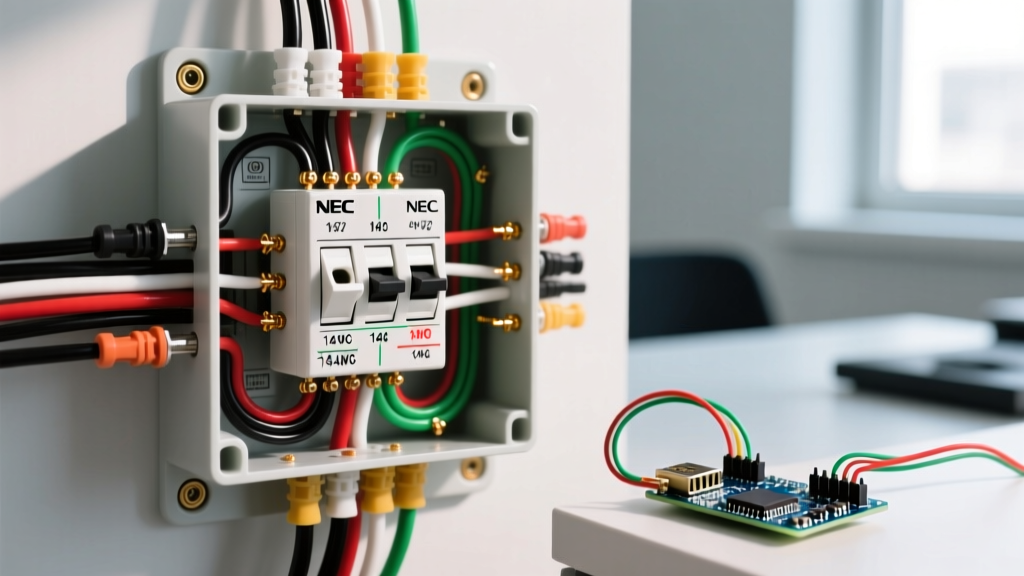
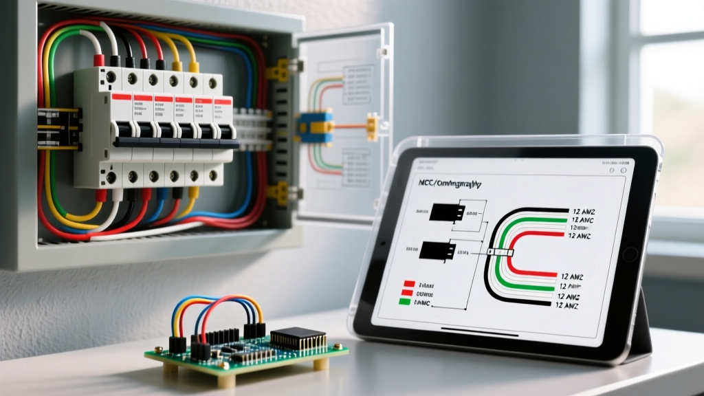
A standard parallel electrical wiring diagram for a 200-amp main service panel illustrates three primary distribution buses that act as the central nodes for all parallel branches:
- Hot Bus Bars (Phases A and B): In a split-phase 240V system, the main breaker feeds two distinct hot bus bars. Each bar carries 120V relative to neutral, and 240V relative to each other. Standard 120V branch breakers clip onto alternating bars to balance the parallel load.
- Neutral Bus Bar: This is the return path for all 120V parallel branches. In a main panel, the neutral bar is bonded to the ground bar and the enclosure. Every white neutral wire from a branch circuit terminates here, completing the parallel circuit back to the utility transformer.
- Ground Bus Bar: Dedicated strictly for equipment grounding conductors (EGC) and the main grounding electrode conductor. It provides a low-impedance parallel path back to the source to facilitate rapid breaker tripping during a ground fault.
Sizing Parallel Branches: Real-World Specifications
When drafting or reading a panel schedule (the textual representation of the parallel wiring diagram), you must match the overcurrent protective device (OCPD) to the wire gauge and the load. As of the 2026 market, here are the standard specifications for residential parallel branches:
15-Amp Lighting and Receptacle Branches
- Wire Gauge: 14 AWG Copper (THHN/THWN-2 or Romex NM-B).
- Breaker Model: Eaton BR115 or Siemens Q115 (Approx. $5.50 - $7.00).
- Application: General lighting, low-draw electronics. NEC Article 210 limits 14 AWG to 15A overcurrent protection.
20-Amp Appliance and Kitchen Branches
- Wire Gauge: 12 AWG Copper.
- Breaker Model: Eaton BR120 or Siemens Q120 (Approx. $6.50 - $8.50).
- Application: Kitchen small appliance circuits, bathroom receptacles, garage outlets.
30-Amp to 50-Amp 240V Parallel Branches
- Wire Gauge: 10 AWG (30A), 8 AWG (40A), 6 AWG (50A) Copper.
- Breaker Model: Siemens Q230 (30A, ~$13.00) or Eaton BR250 (50A, ~$22.00). These are double-pole breakers that span both Phase A and Phase B bus bars to draw 240V.
- Application: Electric dryers, water heaters, EV Level 2 chargers, and HVAC compressors.
The Multi-Wire Branch Circuit (MWBC): A Parallel Trap
One of the most misunderstood elements in a parallel electrical wiring diagram is the Multi-Wire Branch Circuit (MWBC). An MWBC uses two hot wires (one from Phase A, one from Phase B) and a single shared neutral wire to feed two separate 120V parallel branches.
CRITICAL CODE WARNING: Because the two hot legs are 180 degrees out of phase, the currents cancel each other out on the shared neutral. If both branches draw 15A, the neutral carries 0A. However, if an electrician mistakenly lands both hot wires on the SAME phase bus bar, the parallel cancellation fails, and the neutral will carry the combined 30A, melting the 14 AWG wire and causing a fire. NEC 210.4 mandates that MWBCs must have a handle tie or a common-trip double-pole breaker to ensure simultaneous disconnection.
Subpanel Feeder Wiring: Expanding the Parallel Network
When your main panel runs out of physical space, you extend the parallel network by installing a subpanel. The wiring diagram for a subpanel feeder requires strict adherence to separation rules.
Feeder Sizing and Terminations
For a standard 100-amp subpanel located in a detached garage or an addition, the most cost-effective and code-compliant feeder in 2026 is 2-2-2-4 Aluminum SER (Service Entrance) cable. This provides two 2 AWG hot conductors, a 2 AWG neutral, and a 4 AWG ground. A 100A subpanel kit (like the Siemens P2S100) costs roughly $90 to $120.
The Torque Mandate (NEC 110.14(D))
Inspectors in 2026 strictly enforce NFPA 70 (NEC) Section 110.14(D), which requires that all parallel feeder and branch terminations be tightened to the manufacturer's specified torque using a calibrated torque screwdriver. For a 100A main lug, the torque spec is typically 250 to 300 inch-pounds. Hand-tightening with a standard screwdriver leads to thermal expansion/contraction cycles that loosen the connection, increasing resistance and causing catastrophic panel fires.
Isolating Neutrals and Grounds
Unlike the main panel, the parallel wiring diagram for a subpanel strictly prohibits bonding the neutral bar to the ground bar or the enclosure. The neutral must remain completely isolated and float above ground potential, ensuring that normal parallel return currents do not travel back to the main panel via the grounding conductors or metallic conduit.
Troubleshooting Parallel Circuit Failures
Even with a perfect diagram, physical installations degrade. Here are the most common failure modes in parallel panel wiring and how to diagnose them:
| Failure Mode | Symptoms | Diagnostic Action |
|---|---|---|
| Open (Floating) Neutral | Lights brighten and dim when appliances turn on; 120V outlets read anywhere from 40V to 200V. | Check the neutral bus bar for loose terminations. An open neutral causes series-like voltage division across parallel 120V branches. |
| Shared Neutral Violation | Neutral wire overheats; breaker trips intermittently under heavy combined load. | Trace the circuit to ensure MWBC handle ties are present and hots are on opposing phases (A and B). |
| High Resistance Connection | Breaker terminal feels hot to the touch; voltage drop at the furthest receptacle exceeds 3%. | Use a FLIR thermal camera to scan the panel. Re-terminate the wire and apply manufacturer-specified torque. |
Panel Clearance and Safety Standards
Finally, no parallel electrical wiring diagram is complete without accounting for physical working space. According to OSHA Standard 1910.303 and NEC 110.26, you must maintain a minimum clear working space of 30 inches wide and 36 inches deep in front of the panel. This ensures that an electrician can safely measure parallel branch voltages or replace a breaker without standing in an unsafe, cramped environment. Never route plumbing, HVAC ducts, or structural supports through this dedicated parallel distribution zone.
Summary
Mastering the parallel electrical wiring diagram is about more than just connecting wires to breakers; it is about understanding load balancing, phase cancellation, and strict adherence to termination torque specs. By respecting the independent nature of parallel branches and ensuring robust, code-compliant connections at the bus bars, you guarantee a safe, resilient, and efficient power distribution system for any residential or commercial property.