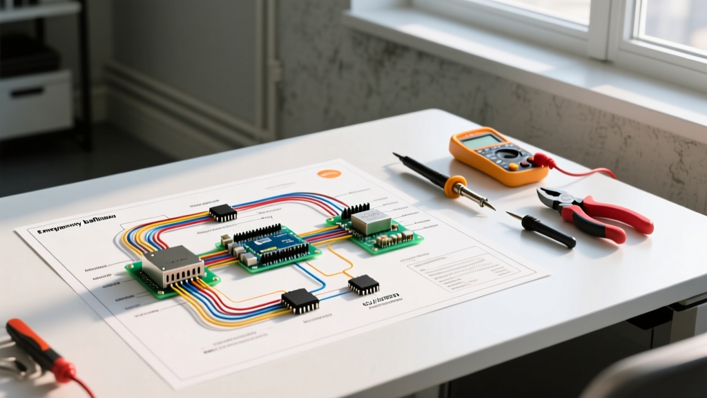

The Critical Role of Emergency Ballasts in Commercial Panels
In commercial and industrial electrical systems, emergency lighting is not just a convenience; it is a life-safety mandate governed by strict building codes. At the heart of many distributed emergency lighting systems is the emergency ballast—a device that integrates a battery backup and transfer switch directly into the lighting fixture. For electrical contractors and panel builders, understanding the wiring diagram for emergency ballast configurations is essential to ensure seamless operation during a grid failure. Unlike standard LED drivers or fluorescent ballasts that only require a single switched or unswitched hot leg, emergency ballasts demand a dual-circuit feed to maintain battery charging while allowing normal wall-switch control. This guide dives deep into the panel and breaker integration requirements, wire sizing, and National Electrical Code (NEC) compliance necessary for a flawless installation in 2026.
Decoding the Wiring Diagram for Emergency Ballast Systems
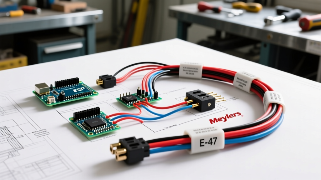
A standard universal emergency ballast (such as the widely used Bodine B-100CG series) operates on 120V-277V AC. When you examine the manufacturer's wiring diagram, you will typically see five or six distinct wire leads emerging from the metal casing. Miswiring these leads is the leading cause of premature battery failure and nuisance breaker tripping.
The Dual-Circuit Requirement: Switched vs. Unswitched
The core complexity of the emergency ballast wiring diagram lies in its need for two separate hot inputs:
- Unswitched Hot (Black Wire): This wire must be connected to a constant, unswitched power source. Its sole purpose is to keep the internal battery fully charged. If this wire is connected to a wall switch, the battery will drain every time the lights are turned off, rendering the emergency system useless during an actual outage.
- Switched Hot (Red Wire): This wire connects to the local wall switch, occupancy sensor, or daylight harvesting relay. It tells the ballast's internal logic whether the user wants the lights on or off during normal grid power.
- Neutral (White Wire): The common return path for both the switched and unswitched circuits.
- Lamp Leads (Blue and Gray/Orange): These output wires connect directly to the LED tubes or fluorescent lamps, bypassing the primary driver when the internal transfer relay switches to battery power.
- Test Switch Lead (Brown Wire): An optional but highly recommended control wire. When connected to a momentary push-button switch and grounded, it simulates a power failure, forcing the ballast to illuminate the lamps on battery power for mandatory 90-minute code testing without needing to shut off the main panel breaker.
NEC Code Callout: According to NFPA 70: National Electrical Code (NEC) Article 411.8 and Article 700.17, the unswitched hot feed for an emergency ballast must be derived from the same branch circuit as the switched hot, or from a dedicated emergency panel with proper mechanical tie-breaker identification. This ensures that if a maintenance worker turns off the breaker to service the fixture, the unswitched charging leg is also de-energized, preventing shock hazards.
Step-by-Step Panel & Breaker Integration
Integrating emergency ballasts into a commercial lighting panel requires careful load calculation and breaker selection. Because these ballasts contain internal inverters and battery charging circuits, they present unique electrical characteristics that standard lighting loads do not.
Breaker Sizing and Inrush Current Calculations
When the grid power is restored after an outage, or when the ballast is first energized, the internal charging circuit draws a significant inrush current to initiate the battery charge cycle. A single 100-watt emergency ballast can draw up to 15 amps of inrush current for a few milliseconds. If you daisy-chain 15 of these ballasts on a standard 20A lighting breaker, the cumulative inrush can trip the breaker's magnetic trip mechanism instantly upon energizing the panel.
| Breaker Rating | Wire Gauge (THHN) | Max Continuous Load | Recommended Max Ballasts (100W Eq.) | Best Application |
|---|---|---|---|---|
| 15A Thermal-Magnetic | 14 AWG | 12A (80% Rule) | 6 to 8 units | Small offices, individual corridors |
| 20A Thermal-Magnetic | 12 AWG | 16A (80% Rule) | 10 to 14 units | Standard commercial ceilings, retail |
| 20A with Inrush Tolerance | 12 AWG | 16A (80% Rule) | 15 to 18 units | High-density warehouse egress paths |
The AFCI and GFCI Dilemma in Emergency Circuits
As of the 2026 NEC cycle, AFCI (Arc-Fault Circuit Interrupter) protection is heavily mandated in commercial dormitories and certain healthcare facilities. However, emergency ballasts can be notoriously problematic on AFCI and GFCI breakers. The high-frequency switching of the internal DC-to-AC inverter during battery mode, combined with the harmonic distortion of the battery charging circuit, can mimic the signature of an arc fault or a ground leakage. Pro Tip: Where local AHJs (Authority Having Jurisdiction) permit, use standard thermal-magnetic breakers for dedicated emergency lighting panels, or utilize specialized lighting-grade AFCI breakers that feature advanced filtering algorithms to ignore inverter harmonics.
Real-World Product Spotlight: Battery Chemistry and Pricing
When specifying the wiring diagram for emergency ballast layouts, the physical hardware you choose dictates long-term maintenance costs. The market has largely shifted from Nickel-Cadmium (NiCad) to Lithium Iron Phosphate (LiFePO4) chemistries.
Bodine B-100CG (NiCad) vs. Signify Bodine B-100CG-L (LiFePO4)
- NiCad Models (e.g., B-100CG): Priced between $110 and $140 per unit. These are the legacy workhorses. However, NiCad batteries suffer from 'memory effect' and typically require complete battery pack replacements every 3 to 5 years to maintain the OSHA 1910.37 mandated 90-minute egress illumination runtime.
- LiFePO4 Models (e.g., B-100CG-L): Priced between $175 and $220 per unit in 2026. While the upfront material cost is higher, Lithium Iron Phosphate batteries offer a 10-year operational lifespan, zero memory effect, and a much wider ambient temperature tolerance (up to 104°F/40°C without severe derating). For new commercial panel build-outs, LiFePO4 is the undisputed standard for reducing total cost of ownership.
For comprehensive product specifications and updated wiring schematics, electrical engineers frequently reference the Signify Bodine Emergency Lighting technical library, which provides exact lumen output degradation charts based on battery age and ambient temperature.
Troubleshooting Edge Cases and Failure Modes
Even with a perfect understanding of the wiring diagram, field conditions can introduce edge cases that cause system failures. Here are the most common failure modes encountered by panel technicians:
- The 'Phantom Blackout' (Miswired Switched Leg): If the red (switched) wire and black (unswitched) wire are swapped at the fixture junction box, the ballast will operate normally when the wall switch is ON. However, when the wall switch is turned OFF, the ballast loses the switched signal but retains the unswitched charge. Depending on the specific logic board, this can cause the lamps to flicker or the internal relay to chatter, eventually burning out the transfer switch contacts.
- Brown Test Wire Ground Faults: The brown test wire is designed to be connected to a momentary switch that routes to ground. If an electrician mistakenly caps the brown wire with a wire nut but leaves a stripped end exposed, and it accidentally touches the metal fixture housing (ground), the ballast will permanently think a power failure is occurring. The lights will stay on continuously until the battery is completely depleted and damaged.
- Voltage Drop on Long Unswitched Runs: In large warehouses, the unswitched hot leg might be pulled from a panel 300 feet away, while the switched leg comes from a local sensor. If 14 AWG wire is used for the unswitched leg, voltage drop can reduce the charging voltage below the ballast's minimum threshold (typically 108V for a 120V nominal system). The ballast will interpret this as a brownout, transfer to battery power, drain the battery, and fail to recharge. Always calculate voltage drop for the unswitched charging leg and upsize to 12 AWG or 10 AWG for runs exceeding 150 feet.
Final Panel Commissioning Checklist
Before energizing the lighting panel, verify the following:
- Confirm that the unswitched hot and switched hot share the same breaker handle tie, or are on the same single-pole breaker.
- Verify that the brown test wire is isolated or properly terminated to a momentary ground switch.
- Measure the AC voltage at the fixture junction box between the black wire and white wire; it must read a stable 120V or 277V (depending on panel phase-to-neutral voltage) with the wall switch in the OFF position.
- Perform a 30-second functional test using the brown wire test switch to ensure the internal transfer relay engages audibly and the lamps illuminate at full emergency brightness.
Mastering the wiring diagram for emergency ballast circuits bridges the gap between standard lighting design and critical life-safety infrastructure. By respecting the dual-circuit requirements, sizing breakers for inrush currents, and selecting modern LiFePO4 hardware, electrical professionals can deliver resilient, code-compliant systems that perform flawlessly when the grid goes dark.