
The Anatomy of a Head Unit to Amplifier Signal Chain
Designing a reliable wiring diagram for car stereo with amplifier integration requires a fundamental understanding of 12V DC power distribution and low-voltage signal routing. Unlike standard residential AC wiring, automotive electrical systems operate in a high-vibration, thermally volatile environment where voltage drop and inductive interference can instantly degrade audio fidelity or cause catastrophic component failure. Modern Class D amplifiers, such as the JL Audio HD1200/1 or Alpine S-A60M, are highly efficient but still demand massive transient current delivery from the vehicle's alternator and battery.
A complete car audio wiring diagram is divided into three distinct circuits: the Power Circuit (battery to amplifier), the Signal Circuit (head unit RCA outputs to amplifier inputs), and the Speaker Circuit (amplifier outputs to transducers). Mismanaging the wire gauge on the power circuit or crossing signal wires parallel to power wires will result in severe alternator whine, thermal shutdown, or clipped signals that destroy voice coils.
Standard CEA Aftermarket Color Code Reference
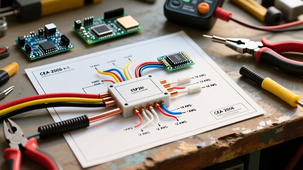
When integrating an aftermarket head unit (like a Pioneer DMH-WT6000NEX or Kenwood eXcelon series) with an external amplifier, adhering to the Consumer Technology Association (CTA) standard color codes is non-negotiable. These standardized colors ensure that harness adapters and direct splices maintain consistent polarity and function across all major brands.
| Wire Color | Function | Voltage / Signal Type | Technical Notes & Best Practices |
|---|---|---|---|
| Yellow | Constant 12V+ (Memory) | 12V DC Continuous | Connects directly to battery or constant fuse. Maintains DSP presets and clock. Must be fused within 18 inches of the power source. |
| Red | Switched 12V+ (Accessory) | 12V DC Ignition | Triggers the head unit on/off. In high-draw systems, use this to trigger a 40A Bosch-style relay rather than drawing directly through the ignition switch. |
| Black | Chassis Ground | 0V Reference | Must be sanded to bare metal and secured with a self-tapping screw or bolt. Never ground to a painted seatbelt bolt. |
| Blue w/ White Stripe | Remote Turn-On (Amp) | 12V DC Low Current | Sends the +12V trigger signal to the amplifier's 'REM' terminal. Max current draw is typically under 300mA. |
| White / White-Black | Front Left Speaker (+/-) | Low-Level Audio | The black stripe always denotes the negative (-) phase. Maintaining absolute phase is critical for soundstage imaging. |
| Gray / Gray-Black | Front Right Speaker (+/-) | Low-Level Audio | Used for high-level inputs on amplifiers lacking RCA pre-outs. Requires a Line Output Converter (LOC) if connecting to DSP. |
| Green / Green-Black | Rear Left Speaker (+/-) | Low-Level Audio | Ensure these do not touch chassis ground, as BTL (Bridge-Tied Load) amplifier outputs will short and trigger protection mode. |
| Purple / Purple-Black | Rear Right Speaker (+/-) | Low-Level Audio | Same BTL warning applies. Use 16 AWG or 14 AWG for speaker runs to minimize resistance over long distances to the trunk. |
Critical Wire Gauge Selection for 12V DC Amplifiers
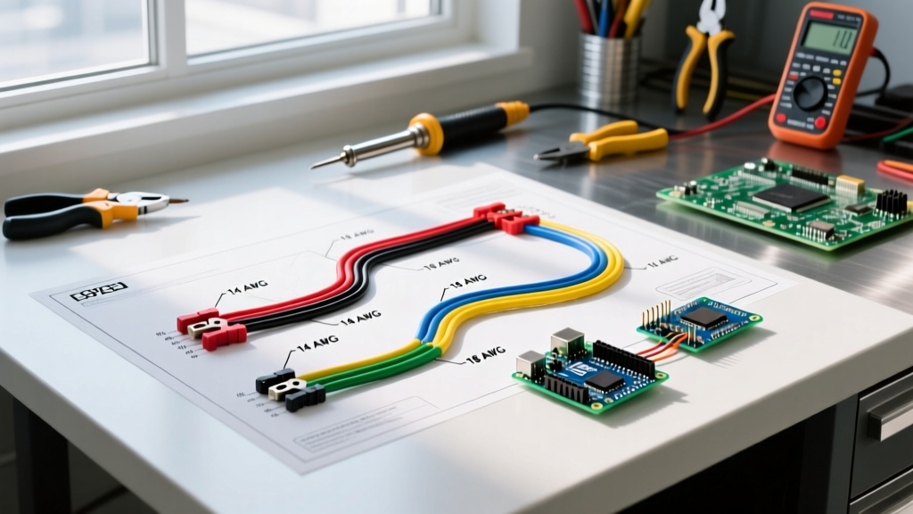
The most frequent point of failure in amateur car audio installations is undersized power wire. According to KnuKoncepts Wire Size Guide, calculating the correct American Wire Gauge (AWG) requires knowing the amplifier's total RMS wattage, the vehicle's charging system voltage (typically 13.8V to 14.4V), and the total length of the power and ground cable run.
The CCA vs. OFC Debate: In 2026, the market is flooded with Copper Clad Aluminum (CCA) wire disguised as pure copper. CCA wire has roughly 40% less conductivity than Oxygen-Free Copper (OFC). A 4 AWG CCA wire performs electrically similar to a 6 AWG OFC wire. For high-current amplifier setups, always demand certified OFC wire to prevent voltage drop and melted insulation under heavy bass transients. Expect to pay between $130 and $180 for a premium 1/0 AWG OFC installation kit, whereas CCA kits sell for $40 to $60.
AWG Sizing Chart for Amplifier Power (OFC Wire)
| Total Amplifier RMS Wattage | 0 - 10 Feet Run | 10 - 16 Feet Run | 16 - 22 Feet Run |
|---|---|---|---|
| 0 - 400 Watts | 8 AWG | 8 AWG | 6 AWG |
| 400 - 800 Watts | 4 AWG | 4 AWG | 4 AWG |
| 800 - 1200 Watts | 4 AWG | 2 AWG | 1/0 AWG |
| 1200 - 2000+ Watts | 1/0 AWG | 1/0 AWG | 2/0 AWG |
Note: Always calculate the total run length by adding the distance from the battery to the amp AND the distance from the amp to the chassis ground point. If utilizing CCA wire, upgrade one full gauge size larger than the chart recommends.
Step-by-Step Routing and Termination Protocol
Executing the wiring diagram for car stereo with amplifier setups requires meticulous attention to physical routing and termination techniques. Follow this standardized protocol to ensure safety and signal integrity.
- Disconnect the Battery: Always remove the negative terminal from the vehicle battery before cutting, stripping, or routing any 12V power cables to prevent dead shorts and ECU damage.
- Main Fuse Placement: Install an ANL or AGU fuse holder on the main positive power wire within 18 inches of the battery positive terminal. This protects the entire vehicle from catching fire if the main power wire shorts against the chassis before reaching the amplifier's internal fuses.
- Firewall Penetration: Route the power cable through an existing factory rubber grommet in the firewall. If you must drill a new hole, use a rubber grommet and apply silicone sealant to prevent exhaust fumes and moisture from entering the cabin.
- Signal vs. Power Separation: Route the RCA signal cables and remote turn-on wire down the opposite side of the vehicle's center console from the main power wire. If the cables must cross, they must intersect at a strict 90-degree angle to minimize inductive coupling and alternator whine.
- Proper Termination: Never wrap bare wire around amplifier set-screws. Use ratcheting crimpers to attach closed-loop ring terminals or spade connectors to all power and ground wires. Seal the connections with adhesive-lined marine-grade heat shrink to prevent copper oxidation.
- Ground Point Preparation: Sand away all paint, primer, and rust from the chassis ground point down to bare, shiny metal. Secure the ground ring terminal with a stainless steel bolt and apply dielectric grease over the terminal to prevent future corrosion.
Troubleshooting Common Amplifier Wiring Failures
Even with a perfect schematic, physical installation variables can introduce complex electrical faults. Use this diagnostic matrix to resolve common issues.
1. Alternator Whine (Pitch Changes with RPM)
Root Cause: Ground loop interference or inductive coupling. The amplifier and head unit are referencing different ground potentials, or the RCA cables are picking up electromagnetic interference (EMI) from the power wire or ignition harness.
Solution: Verify that the head unit and amplifier share a common ground plane. If the issue persists, inspect the RCA cables for broken shielding. As a last resort, install a ground loop isolator (like the PAC GLI-2) on the RCA lines, though this can slightly attenuate high-frequency response.
2. Amplifier Enters 'Protect' Mode Under Heavy Bass
Root Cause: Severe voltage drop. When a subwoofer demands a 50-amp transient burst, undersized wire or a poor ground causes the voltage at the amplifier's B+ terminal to drop below the operational threshold (usually 10.5V), triggering the internal protection micro-circuit.
Solution: Measure the voltage at the amplifier's power terminals using a digital multimeter while playing a 40Hz bass tone at high volume. If voltage drops below 11.5V, upgrade to a larger OFC wire gauge, add a secondary battery in the trunk, or install a lithium-ion car audio capacitor bank.
3. Head Unit Fails to Power On After Installation
Root Cause: Blown internal PCB trace or accessory fuse. This typically occurs when the 'Blue/White' remote wire is incorrectly spliced into a high-current circuit (like a cooling fan or power window relay), back-feeding voltage into the head unit's delicate 12V trigger transistor.
Solution: Always use the dedicated 'Blue/White' wire for amplifier triggers. If the head unit's remote output is already damaged, bypass it by using the vehicle's accessory fuse box with an 'Add-A-Circuit' (fuse tap) to trigger a standard 12V automotive relay, which then sends power to the amplifier's REM terminal.
Expert Insight: According to Crutchfield's Amplifier Installation Guide, the vast majority of 'blown amplifier' warranty returns are actually the result of improper impedance wiring or clipped signals from an over-driven head unit, rather than manufacturing defects. Always match the amplifier's minimum stable ohm load to the final DVC (Dual Voice Coil) wiring configuration of your subwoofers.
Final Verification and System Biasing
Before reassembling the vehicle's interior trim, perform a final continuity and voltage check. Reconnect the battery and use a multimeter to verify that the main power wire reads 12.6V (engine off) and 13.8V to 14.4V (engine running). Set the amplifier's gain potentiometer using a digital storage oscilloscope (DSO) or an AC voltage multimeter to match the head unit's maximum unclipped pre-out voltage (typically 2V to 4V RMS). Properly setting the gain ensures the amplifier delivers clean, unclipped power, protecting your subwoofers from thermal failure and ensuring the longevity of your entire car audio investment.