
Decoding the Wiring Diagram for 2 Switches
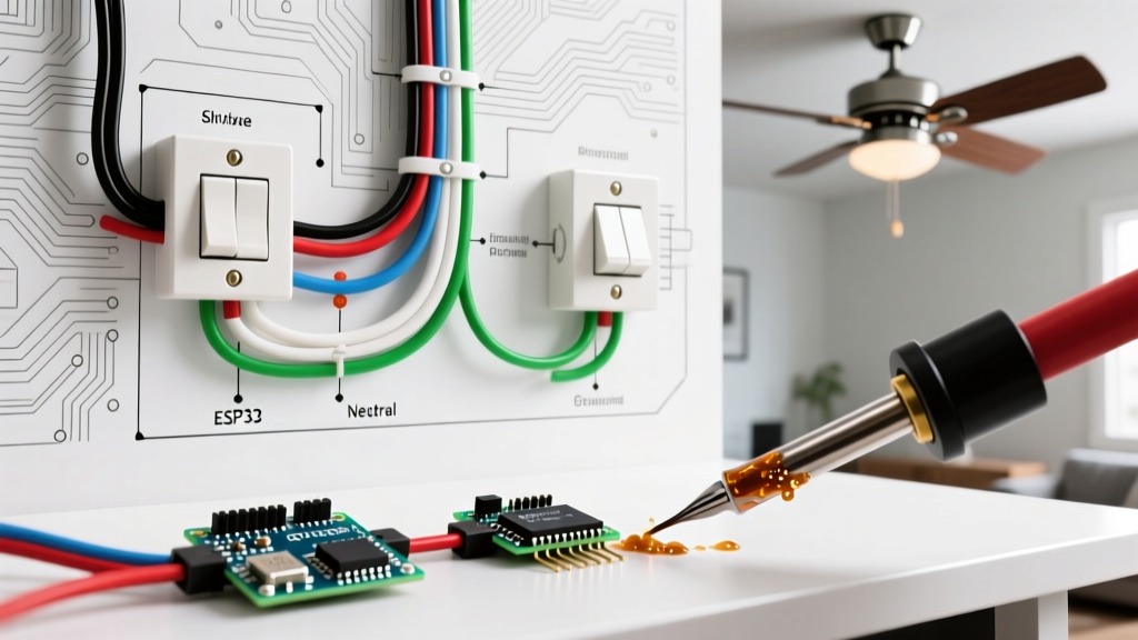
When homeowners, DIY enthusiasts, and apprentice electricians search for a wiring diagram for 2 switches, they are typically trying to solve one of two distinct electrical scenarios. The first is a 3-way switch circuit, which allows a single light fixture to be controlled from two separate physical locations (like the top and bottom of a staircase). The second is a double-gang single-pole setup, where two separate switches reside in the same wall box to control two independent light fixtures or a light and a ceiling fan.
Understanding the exact topology of your circuit is critical. Misinterpreting these diagrams can lead to short circuits, tripped AFCI breakers, or severe shock hazards. This comprehensive reference guide breaks down both configurations with exact product specifications, National Electrical Code (NEC) requirements, and modern 2026 best practices for safe termination.
⚠️ Critical Safety Prerequisite: Before removing any faceplate, turn off the circuit breaker and verify the absence of voltage using a non-contact voltage tester like the Fluke 1AC-II VoltAlert. Never rely solely on the switch position. For detailed safety protocols, always consult the OSHA Electrical Safety Guidelines.Scenario A: The 3-Way Switch (One Light, Two Locations)
A 3-way switch setup requires specialized hardware. You cannot use standard single-pole switches for this configuration. You must use two 3-way switches, such as the Leviton Decora 5603 (15 Amp) or the Leviton 5604 (20 Amp). Unlike single-pole switches, 3-way switches do not have 'ON' and 'OFF' markings; instead, they feature three terminal screws (excluding the green ground screw).
Terminal Identification and Wire Roles
The most common point of failure in a 3-way circuit is misidentifying the 'Common' terminal. On a Leviton 3-way switch, the Common terminal is the black screw, while the two 'Traveler' terminals are the brass screws. The ground screw is green.
| Wire Color (NM-B Cable) | Function in 3-Way Circuit | Termination Point |
|---|---|---|
| Black (Hot) | Line (Power Source) or Load (To Fixture) | Common Terminal (Black Screw) |
| Red | Traveler 1 | Brass Screw 1 |
| White (Re-identified) | Traveler 2 | Brass Screw 2 |
| Bare Copper | Equipment Ground | Green Screw & Metal Box |
NEC Code Note: Per the NFPA 70 National Electrical Code (Article 200.7), if you use a 14/3 or 12/3 NM-B cable between the two switches, the white wire must be permanently re-identified as a hot conductor (using black or red electrical tape) at both ends, as it is acting as a traveler, not a neutral.
Step-by-Step 3-Way Wiring Sequence
- Prepare the Cables: Strip 3/4 inch of the outer NM-B jacket using a Klein Tools 11063 cable ripper. Strip 1/2 inch of insulation from the individual conductors using the Klein 11055 wire strippers.
- Wire the Line Switch (Switch 1): Connect the incoming black hot wire from the breaker panel to the black Common screw. Connect the red and white (taped black) wires of the 14/3 traveler cable to the two brass screws. The order of the travelers does not matter.
- Wire the Load Switch (Switch 2): Connect the black wire of the 14/3 traveler cable to the black Common screw. This black wire will continue up to the light fixture as the switched hot. Connect the red and white (taped black) traveler wires to the brass screws.
- Terminate Grounds: Pigtail all bare copper ground wires together using a WAGO 221-3 Lever-Nut and run a single ground pigtail to the green screw on each switch and to the metal box if applicable.
Scenario B: Double Gang Box (Two Lights, One Location)
The second interpretation of a wiring diagram for 2 switches involves a double-gang wall box housing two independent single-pole switches. This is common in kitchens (controlling under-cabinet lights and overhead cans) or bathrooms (controlling the vanity light and exhaust fan).
The Pigtailing Method vs. Shared Terminals
Beginners often attempt to daisy-chain the hot wire by inserting two wires under a single terminal screw or using the push-in backstab connectors. Do not do this. Backstab connectors are notorious for arcing and failing under continuous load. Furthermore, most modern single-pole switches (like the Leviton 5601 Decora) only allow one wire per terminal screw.
The professional standard in 2026 is the pigtail method. You will connect the incoming hot wire, the hot wire feeding the second switch, and a short 6-inch pigtail wire together using a WAGO 221-3 lever connector. The other end of the pigtail connects to the brass terminal on the first switch. This ensures a secure, high-surface-area connection and maintains continuous power to the second switch without relying on the switch body to pass current.
Box Fill Calculations (NEC 314.16)
When installing two switches in a single box, box fill becomes a critical safety calculation. Overcrowding a box causes heat buildup and damages wire insulation. According to NEC Chapter 9, Table 1, each 14 AWG conductor counts as 2.0 cubic inches, and each 12 AWG conductor counts as 2.25 cubic inches.
- 14 AWG Setup (15A Circuit): A double gang box with two 14/2 cables entering, two single-pole switches, and internal clamps requires a minimum box volume of approximately 34 cubic inches. Use a deep PVC box like the Carlon B618R-UPC (34 cu in) or a 4x2x2.5 inch steel masonry box.
- 12 AWG Setup (20A Circuit): The volume requirement increases. Ensure your box is rated for at least 38 cubic inches to accommodate the thicker 12 AWG insulation and larger WAGO connectors.
Expert Insight: In 2026, the use of WAGO 221 Series Lever-Nuts is heavily preferred over traditional twist-on wire nuts for pigtailing in tight double-gang boxes. They require less wire length (stripped to exactly 11mm), provide a transparent housing for visual inspection, and eliminate the torque-related failures common with improperly installed wire nuts.
Upgrading to Smart Switches: The Lutron Caseta Advantage
Upgrading a 2-switch 3-way circuit to smart home control traditionally required rewiring the travelers or installing complex micro-modules. Today, the Lutron Caseta Claro (PD-5S-DV) simplifies the wiring diagram for 2 switches drastically. In a smart 3-way setup, you replace the primary switch with the Caseta smart switch, and replace the secondary 3-way switch with a Lutron Pico Remote mounted in a wallbox adapter.
This completely eliminates the need for traveler wires. The Caseta switch only requires Line, Load, Neutral, and Ground. The secondary location simply houses the Pico remote, which communicates via Lutron's proprietary Clear Connect RF protocol. This is the ultimate solution for older homes where the 3-way traveler wires are damaged, missing, or improperly spliced inside the walls.
Troubleshooting Common 2-Switch Failures
Even with a perfect wiring diagram for 2 switches, physical installation errors occur. Here is a diagnostic matrix for the most frequent issues:
| Symptom | Probable Cause | Diagnostic Fix |
|---|---|---|
| 3-Way switches only work from one location. | The Line or Load wire is incorrectly terminated on a brass Traveler screw instead of the black Common screw. | Identify the always-hot wire with a multimeter and move it to the black Common screw. |
| AFCI/GFCI breaker trips immediately upon switching. | Shared neutral fault or bootleg ground (neutral bonded to ground at the switch). | Verify the neutral white wires are not touching the ground bundle or the metal box. |
| Switch feels warm to the touch. | Loose terminal connection causing high resistance and arcing, or overloaded 14 AWG wire on a 20A breaker. | Check breaker amperage. Re-terminate wires using the screw terminals, ensuring no bare copper is exposed outside the terminal. |
Frequently Asked Questions
Can I use a 14/2 wire between the two 3-way switches?
No. A standard 3-way circuit requires a 14/3 (or 12/3) NM-B cable between the two switch locations to accommodate the two traveler wires and the common wire. Using 14/2 will leave you short a conductor, forcing unsafe code violations like using the bare ground wire as a current-carrying traveler, which is strictly prohibited by the NEC and poses a lethal shock hazard.
Does it matter which brass screw the red and black traveler wires connect to?
No. The two brass screws on a 3-way switch are electrically symmetrical regarding the travelers. Swapping the red and black traveler wires between the two brass screws will not affect the operation of the circuit. However, you must never swap a traveler with the common (black screw) wire.
Do I need to ground the switch if the box is plastic?
Yes. Per NEC 404.9(B), a snap-in switch must be grounded. Even in a non-metallic (plastic) box, you must connect the bare copper ground wire from the NM-B cable directly to the green ground screw on the switch yoke. The only exception is if you are using a 'No-Ground' replacement switch (identified by a 'No Equipment Ground' label) in an older home where no ground wire exists in the wall, which requires a GFCI upstream for protection.