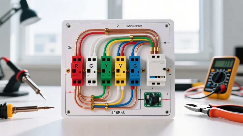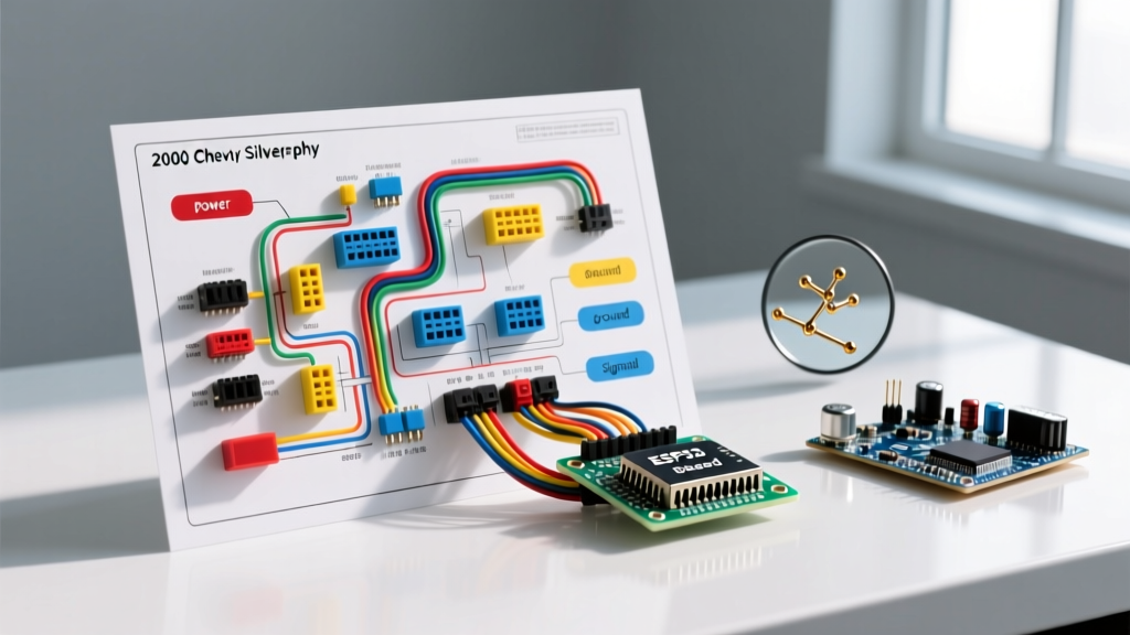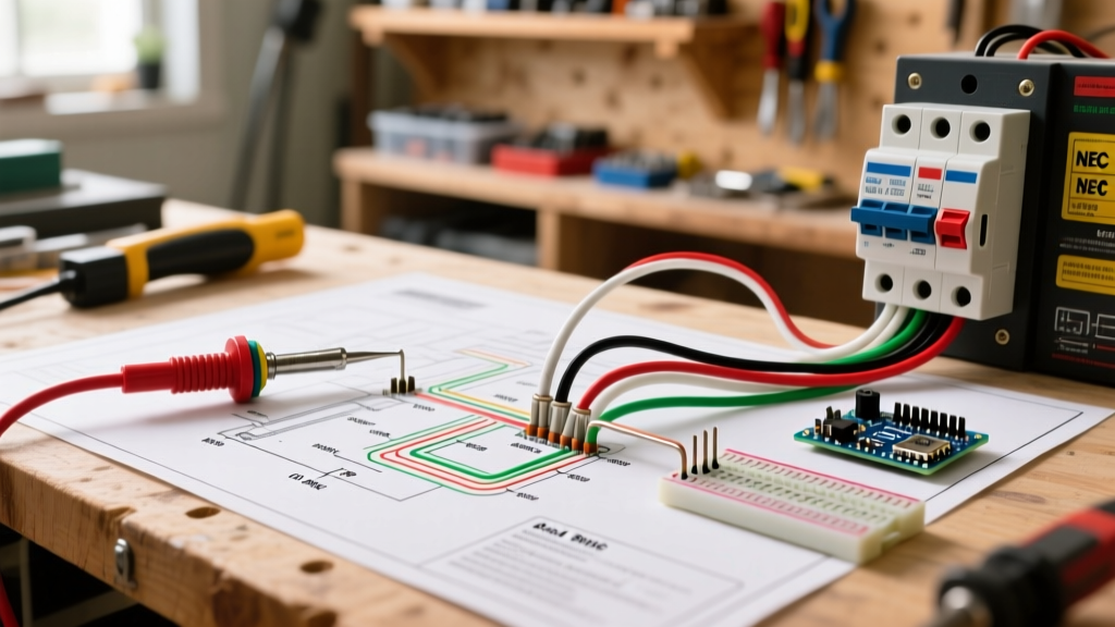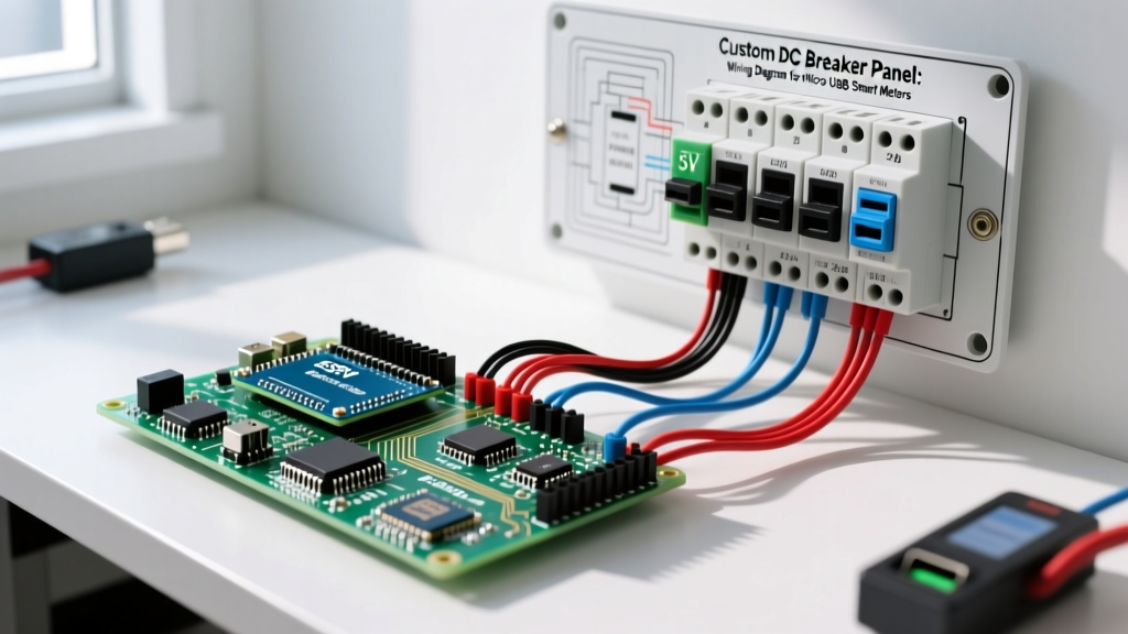

The 2026 Smart DC Panel: Bridging High Current and Micro USB
In modern off-grid solar installations, RV builds, and IoT workshop environments, DC distribution panels are no longer just passive breaker boxes. The standard in 2026 involves integrating smart DIN-rail panel meters, ESP32-based data loggers, and automated relays directly into the breaker enclosure. However, a significant design friction point arises: while the main DC bus operates at 12V, 24V, or 48V, many of the most cost-effective and highly accurate smart monitoring modules rely on 5V power and serial data routed via micro USB.
Finding a reliable wiring diagram for micro usb integration into a high-current DC breaker panel is crucial. Improper integration leads to severe voltage drops, ground loop interference, and catastrophic failure of low-voltage logic boards. This guide provides a professional-grade framework for safely stepping down DC panel voltage, fusing the 5V branch, and properly terminating fragile micro USB pigtails into DIN-rail terminal blocks.
Core Component Bill of Materials (BOM)
To build a robust 5V micro USB branch circuit inside a standard DC breaker panel, you must avoid cheap, unregulated buck converters. Thermal management and isolation are paramount when mixing 24V DC mains with 5V logic.
- Power Supply: Mean Well DR-15 DIN-rail series (Specifically the DR-15-5, 5V 3A output). Retail price: ~$18.50. This provides isolated, regulated 5V power with built-in overload and short-circuit protection.
- Terminal Blocks: Wago 2016 Series TopJob S (e.g., 2016-1311). Retail price: ~$2.10 each. Critical: Unlike the standard 2002 series, the 2016 series accepts wire gauges down to 28 AWG, which is essential for micro USB pigtails.
- Fuse Protection: Phoenix Contact QTC DIN-rail fuse terminals with 5x20mm fast-acting glass fuses (rated 1A to 2A depending on the meter draw).
- Interconnect Wire: 20 AWG stranded silicone wire for the 5V bus routing, and 28 AWG micro USB breakout pigtails.
- Ferrules: Phoenix Contact AI 0.25-6 YE (0.25mm² / 28 AWG ferrules) to prevent strand fraying during termination.
Step-by-Step Wiring Diagram for Micro USB Integration
The following procedure outlines how to route power from a 24V DC main bus to a micro USB-powered smart panel meter mounted on the DIN rail.
Phase 1: Stepping Down the DC Bus
- Main Bus to Breaker: Run 10 AWG (or appropriately sized) wire from your main 24V DC positive busbar to a dedicated 10A DC breaker (e.g., a Bussmann or Blue Sea Systems magnetic-hydraulic breaker).
- Breaker to Power Supply: Route the output of the 10A breaker to the V+ input terminal on the Mean Well DR-15-5. Connect the negative DC busbar directly to the V- input terminal using 14 AWG wire.
- Earth Grounding: Connect the DR-15-5 grounding screw directly to the panel's PE (Protective Earth) busbar using 12 AWG green/yellow wire. This ensures chassis safety and shields the 5V output from high-frequency switching noise.
Phase 2: Fusing and Routing the 5V Branch
- 5V Output to Fuse: Connect the V+ OUT of the Mean Well to the input side of a Phoenix Contact QTC fuse terminal block using 20 AWG red silicone wire.
- Fuse Sizing: Insert a 1.5A fast-acting glass fuse. Most micro USB smart meters draw between 200mA and 800mA; a 1.5A fuse protects the delicate 28 AWG USB wiring from melting in the event of a short circuit.
- 5V Distribution Bus: Use Wago 2016 multi-level terminal blocks or standard feed-through blocks to create a dedicated 5V positive bus and a 5V DC negative (Ground) bus. Do not mix the 5V ground with the main 12V/24V negative busbar unless the power supply is non-isolated (the DR-15 is isolated, so keep them separate to prevent ground loops).
Phase 3: Terminating the Micro USB Pigtail
Many ESP32-based DIN-rail meters feature a micro USB port for 5V power and UART serial data. To hardwire this into the panel without relying on bulky USB cables:
- Purchase a Micro USB to bare wire pigtail (ensure it is rated for data + power, containing 4 internal conductors: VBUS, D-, D+, GND).
- Strip the outer jacket to expose the 28 AWG wires. The standard micro USB pinout is: Pin 1 (Red): VBUS (5V), Pin 2 (White): D-, Pin 3 (Green): D+, Pin 5 (Black): GND. (Pin 4 is ID and usually left floating).
- Strip 6mm of insulation from the Red and Black wires. Crimp 0.25mm² (28 AWG) bootlace ferrules onto the strands.
- Terminate the Red (VBUS) wire into the fused 5V positive terminal block, and the Black (GND) wire into the 5V negative terminal block.
Expert Tip: Never attempt to solder 28 AWG micro USB wires directly to a panel meter's PCB if a port is available. Vibration in mobile DC panels (like RVs or marine vessels) will quickly cause solder-joint fatigue and rip the micro USB port off the board. Strain-relieve the pigtail using a cable tie mounted to the DIN rail before termination.
Wire Gauge, Breaker, and Fuse Matrix
Proper overcurrent protection is dictated by the smallest wire gauge in the circuit. Use this matrix to size your protection devices when integrating low-voltage USB components into high-current panels.
| Circuit Segment | Wire Gauge | Max Continuous Current | Protection Device | Use Case |
|---|---|---|---|---|
| Main DC Bus to 5V PSU | 14 AWG | 15A | 10A DC Breaker | Feeding the Mean Well DR-15-5 input |
| 5V PSU to 5V Bus | 20 AWG | 5A | 3A Fast Fuse | Main 5V distribution routing |
| 5V Bus to Micro USB | 28 AWG | 0.8A | 1A or 1.5A Fast Fuse | Individual smart meter / ESP32 node |
| USB Data Lines (D+/D-) | 28 AWG | N/A (Signal) | None (Use TVS Diode) | RS485 / UART data logging |
Edge Cases: Ground Loops and Data Noise
When your wiring diagram for micro usb includes data lines (D+ and D-) for serial communication to a central Raspberry Pi or PLC hub, signal integrity becomes a major challenge inside a breaker panel full of switching relays and inverters.
The Ground Loop Trap
If your central data hub is powered by a separate 120V AC-to-DC adapter, and your panel meters are powered by the Mean Well DR-15-5, connecting the micro USB data lines will tie the two different 5V ground references together. Because the panel environment is electrically noisy, this creates a ground loop, resulting in corrupted serial packets or fried UART chips.
The Solution: Use an isolated USB hub (such as the Exsys EX-1188HMS) mounted on the DIN rail, or utilize digital isolators (like the Texas Instruments ISO7741) between the micro USB data lines and the central hub. According to Victron Energy's Wiring Unlimited guide, keeping low-voltage signaling physically separated from high-current DC busbars by at least 100mm (4 inches) is also mandatory to prevent electromagnetic interference (EMI).
Safety Standards and Code Compliance
While a 5V micro USB circuit seems inherently safe, integrating it into a panel that houses 24V or 48V DC mains subjects it to specific electrical codes. Under the National Electrical Code (NEC), specifically Article 725 covering Class 1, Class 2, and Class 3 Remote-Control, Signaling, and Power-Limited Circuits, the 5V micro USB wiring qualifies as a Class 2 circuit.
NEC Article 725.136 requires that Class 2 circuits (the 5V USB power and data) must be separated from Class 1 or power circuits (the 12V/24V DC mains) by a minimum of 2 inches, or by a physical barrier (such as a grounded metal divider or an insulating partition). When routing your 28 AWG micro USB pigtails, ensure they do not cross over or run parallel in the same wire duct as the 10 AWG main DC feeders without a divider. This separation prevents a catastrophic fault where a frayed 24V wire could short into the 5V micro USB line, instantly destroying your smart monitoring network and posing a severe fire hazard.
Final Panel Commissioning Checklist
- Verify the Mean Well DR-15-5 output is exactly 5.0V to 5.1V using a multimeter before plugging in any micro USB smart meters.
- Tug-test all 28 AWG ferrule connections in the Wago 2016 terminal blocks to ensure the tiny strands are fully captured.
- Confirm physical separation (minimum 2 inches) between the 5V micro USB data lines and the main DC busbars.
- Test the 1.5A branch fuses by intentionally shorting a dummy 5V load to ensure the glass fuse blows before the 28 AWG wire heats up.