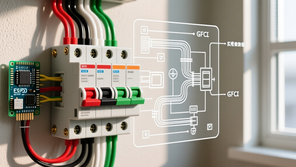

Decoding the Electrical Wiring Breaker Box Diagram
When a residential or light-commercial power system exhibits erratic behavior, the electrical wiring breaker box diagram is your primary roadmap. Unlike simple receptacle wiring, a load center involves complex phase balancing, neutral-to-ground bonding, and increasingly sophisticated microprocessor-based protection. Troubleshooting without referencing the panel schematic and circuit directory often leads to misdiagnosed faults, unnecessary part replacements, and severe arc-flash hazards.
In 2026, the modernization of the NFPA National Electrical Code (NEC) mandates widespread use of Dual-Function (AFCI/GFCI) breakers and strict torque specifications for all terminations. This guide provides a deep-dive framework for using breaker box diagrams to isolate and resolve complex electrical faults safely and efficiently.
The Anatomy of a Panel Diagram
Before opening the dead front, you must understand the two distinct diagrams associated with your panel:
- The Panel Schedule (Circuit Directory): Maps the physical breaker slots to the downstream loads. It dictates phase assignment (L1 vs. L2) and identifies Multi-Wire Branch Circuits (MWBCs).
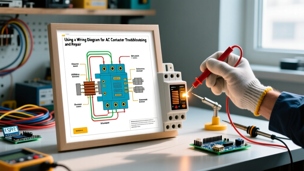
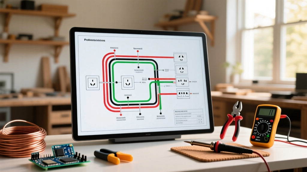
- The Internal Schematic (Wiring Diagram): Usually printed on the inside of the panel door or dead front. It illustrates the routing of the main service conductors, the neutral bus bar, the equipment grounding bus bar, and the main bonding jumper. This is critical for identifying where neutral and ground paths diverge.
Expert Insight: Never rely solely on the previous electrician's handwritten panel schedule. Always verify the physical wiring against the internal schematic using a non-contact voltage tester and a digital multimeter before assuming a circuit is de-energized or correctly phased.
Top 3 Breaker Box Faults & Diagram Mapping
Fault 1: The 'Floating' Neutral (Loose Bus Bar Termination)
Symptoms: Lights flicker when heavy appliances cycle. Multimeter readings at 120V receptacles fluctuate wildly between 90V and 145V.
Diagram Diagnosis: Refer to the internal schematic to locate the main neutral bus bar. A loose neutral lug at the main bus or a sub-panel feed causes the series-parallel voltage divider effect across the 240V split-phase system.
The Fix: De-energize the main breaker. Use a calibrated torque screwdriver (e.g., Klein Tools 32500TORQ) to tighten the neutral lugs. For standard Square D Homeline panels, #14-#10 AWG copper wires require exactly 35-50 in-lbs of torque, while main service lugs require up to 120-150 in-lbs depending on the wire gauge. Under-torquing causes thermal expansion failures; over-torquing strips the aluminum bus threads.
Fault 2: Multi-Wire Branch Circuit (MWBC) Miswiring
Symptoms: The shared neutral wire is melting or discolored at the panel, yet the individual 20A breakers (e.g., standard Eaton BR220) never trip.
Diagram Diagnosis: Check the panel schedule. An MWBC requires two hot wires connected to opposite phases (L1 and L2) to cancel out the return current on the shared neutral. If the diagram shows the breakers are on the same phase (e.g., slots 1 and 3 on some older panels, rather than 1 and 2), the neutral carries the additive sum of both circuits, easily exceeding its 20A ampacity without tripping the hot breakers.
The Fix: Relocate one breaker to an adjacent slot on the opposite bus stab. Install an approved handle tie (e.g., Eaton HT1RK) or replace the two single-pole breakers with a single 2-pole breaker to ensure simultaneous disconnect, as mandated by NEC Article 210.4.
Fault 3: Nuisance Tripping in AFCI/GFCI Breakers
Symptoms: A Dual-Function breaker (e.g., Siemens QAF220 or Square D HOM120DF) trips immediately upon reset or when a specific load is turned on.
Diagram Diagnosis: AFCI/GFCI breakers monitor the vector sum of the current on the hot and the dedicated neutral. If the panel diagram reveals that a downstream circuit shares a neutral with another circuit (a 'borrowed neutral'), or if the neutral and ground are bonded downstream of the main panel, the breaker detects an imbalance and trips.
The Fix: Trace the schematic to ensure the pigtail neutral of the AFCI/GFCI breaker connects exclusively to the correct neutral bus bar, and that the downstream load's neutral returns directly to that specific breaker's neutral terminal, not the bus bar. Separate any crossed neutrals in downstream junction boxes.
Diagnostic Tool Matrix for Panel Troubleshooting
| Tool | Specific Model Example | Application in Breaker Box | Expected Reading / Spec |
|---|---|---|---|
| Digital Multimeter (True RMS) | Fluke 117 | Measuring L1-N, L2-N, and L1-L2 voltages to detect floating neutrals. | 120V ±5% (L-N), 240V ±5% (L-L) |
| Thermal Imaging Camera | FLIR E54 or Seek CompactPRO | Scanning bus bars and breaker terminals for hotspots under load. | Delta T < 10°C above ambient |
| Torque Screwdriver | Milwaukee 48-22-7525 | Verifying termination torque on breaker lugs and neutral/ground bars. | 35-50 in-lbs (Branch), 120+ in-lbs (Main) |
| Circuit Tracer | Amprobe AT-3500 | Identifying unmarked or mislabeled circuits on the panel schedule. | N/A (Signal identification) |
Step-by-Step Troubleshooting Workflow
Follow this structured protocol to ensure safety and accuracy when diagnosing panel faults:
- Visual & Thermal Inspection (Live): With the panel cover on but the door open, use a thermal camera to scan for hotspots. A breaker terminal reading 40°C hotter than adjacent breakers indicates a loose wire termination or internal breaker contact failure.
- Voltage Verification (Live): Measure Line-to-Neutral and Line-to-Line voltages at the main lugs. If L1-N is 135V and L2-N is 105V, you have a compromised utility neutral or a loose main neutral lug. Stop and contact the utility company if the fault is upstream of the main breaker.
- De-energize and Lockout/Tagout (LOTO): Turn off the main breaker. Apply a LOTO device to prevent accidental re-energization. Verify zero voltage at the branch breakers using a CAT III or CAT IV rated multimeter.
- Mechanical Verification (Dead): Using your torque screwdriver, check all branch circuit hot and neutral terminations. Inspect the neutral and ground bus bars for signs of arcing, melting, or oxidation.
- Continuity & Isolation Testing (Dead): If troubleshooting an AFCI/GFCI trip, disconnect the downstream hot and neutral. Test for continuity between the downstream neutral and the ground wire. Any continuity indicates an illegal neutral-to-ground bond downstream.
When to Repair vs. Upgrade the Panel
Troubleshooting can only go so far if the physical infrastructure is obsolete. Here is a 2026 cost-benefit framework for deciding between repair and replacement:
- Repair (Cost: $150 - $400): Ideal if the panel bus bars are in good condition, but specific breakers have failed or terminations have loosened. Replacing a failed 20A Dual-Function CAFCI/GFCI breaker costs between $65 and $85. Retorquing connections and cleaning oxidation costs only labor.
- Upgrade (Cost: $2,200 - $3,800): Mandatory if you have a recalled panel (e.g., Federal Pacific Stab-Lok or Zinsco), if the bus bars show severe pitting/arcing, or if you need to expand from 100A to 200A to support modern loads like EV Level 2 chargers (which require a dedicated 60A 240V circuit) and heat pumps. A new 200A Square D QO or Eaton BR main breaker panel enclosure costs roughly $250-$350, but the labor, permitting, and utility coordination drive the total price.
Safety and Compliance Directives
WARNING: Working inside an electrical wiring breaker box exposes you to the main service lugs, which remain energized by the utility grid even when the main breaker is in the OFF position. According to OSHA Electrical Safety Guidelines, only qualified personnel wearing appropriate PPE (Arc-rated clothing, insulated gloves, and face shields) should perform live diagnostics on service equipment. Always adhere to NFPA 70E standards for arc-flash boundary calculations.
Furthermore, the Consumer Product Safety Commission (CPSC) strongly recommends the installation of AFCI protection on all 120V, 15A and 20A branch circuits supplying living areas to mitigate electrical fire risks. When troubleshooting older panels that lack these protections, upgrading to modern dual-function breakers should be a primary recommendation in your diagnostic report.
Summary
Mastering the electrical wiring breaker box diagram transforms troubleshooting from a guessing game into a precise, data-driven science. By cross-referencing the panel schedule with the internal schematic, verifying torque specifications, and utilizing thermal diagnostics, you can accurately isolate floating neutrals, MWBC phase errors, and AFCI nuisance trips. Always prioritize safety, adhere to the latest NEC mandates, and recognize when a panel's physical degradation necessitates a full upgrade rather than a simple repair.