
Decoding the Schematic: Beyond Basic Installation
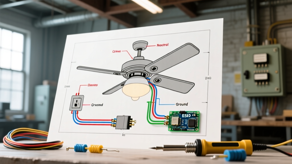
When a newly installed or aging fixture malfunctions, the wiring diagram for a ceiling fan with a light transitions from a simple installation map to a critical diagnostic tool. Most homeowners and even junior electricians view these schematics merely as a guide for connecting colored wires. However, from a troubleshooting perspective, the diagram reveals the logical flow of current through the canopy receiver, the downrod, the switch housing, and the light kit assembly.
In 2026, the landscape of ceiling fan wiring has bifurcated. Traditional dual-switch mechanical setups now coexist with integrated WiFi smart drivers that eliminate the need for bulky RF canopy receivers. To effectively troubleshoot, you must first identify which architectural generation your diagram represents, then use a digital multimeter (such as a Fluke 117) to isolate the exact point of failure.
The Anatomy of the Circuit: Standard Color Codes
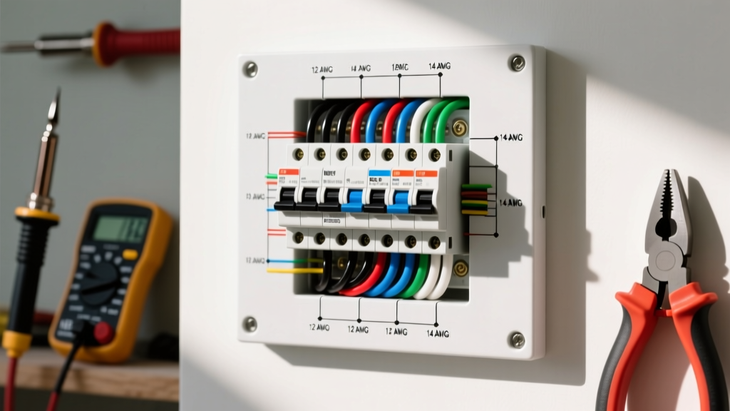
Before diving into fault isolation, verify the baseline wire functions. While manufacturers like Hunter, Hampton Bay, and Minka-Aire have slight variations, the standard North American color code for a dual-function fixture remains consistent:
- Black (Ceiling) to Black (Fan): 120V AC Hot for the fan motor.
- Black (Ceiling) to Blue (Fan): 120V AC Hot for the light kit (in single-switch setups).
- White to White: Neutral return path.
- Green/Bare to Green/Bare: Equipment grounding conductor.
Expert Insight: If your wiring diagram for a ceiling fan with a light shows a red wire coming from the ceiling, your home is pre-wired for dual-wall switches. The black wall wire controls the motor, and the red wall wire controls the blue light kit wire independently.
Diagnostic Matrix: Symptom vs. Wiring Fault
Use this matrix to cross-reference your physical symptoms with potential schematic mismatches. This eliminates guesswork and prevents unnecessary component replacements.
| Observed Symptom | Likely Diagram Mismatch | Multimeter Verification Step |
|---|---|---|
| Fan hums but blades do not spin | Blue and Black wires swapped at canopy; motor receiving incorrect voltage pathway. | Test continuity between ceiling black and fan black. Check run capacitor for microfarad degradation. |
| Light works, fan is completely dead | Open circuit on the black hot wire; loose wire nut at the switch housing. | Measure AC Voltage between fan black wire and white neutral. Should read ~120V. |
| Fan works, light is dead | Blue wire not pigtailed to black (single switch) or receiver module failure. | Check 120V at the blue wire connection point inside the light kit switch cup. |
| Both trip the breaker instantly | Hot wire (Black/Blue) shorted to Ground (Green/Bare) or crushed insulation in downrod. | Set meter to Continuity. Test between Hot and Ground with breaker OFF. Beep indicates dead short. |
Scenario 1: The Single-Switch vs. Dual-Switch Dilemma
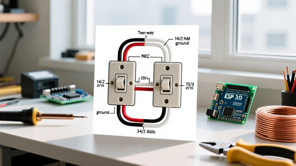
One of the most common troubleshooting calls involves a fixture where the fan and light only operate simultaneously, despite the homeowner wanting independent control. When you consult the wiring diagram for a ceiling fan with a light, you will typically see two options for the hot wire connection at the canopy.
The Single-Pole Switch Setup
If your ceiling electrical box only contains one hot wire (usually black) and one neutral (white), the diagram dictates that you must connect both the fan's black wire and the fan's blue wire to the single ceiling black wire. In this scenario, the wall switch controls power to the entire unit. Independent operation is only possible if the fixture includes a pull-chain or a remote-control receiver module.
The Dual-Switch Setup
If your diagram shows a red wire from the ceiling, but you only have a black wire, you have a wiring mismatch. You cannot achieve independent wall control without running a new 14/3 or 12/3 Romex cable from the switch box to the ceiling box. Attempting to force a smart switch into a single-hot-wire box to control both functions independently will fail unless the switch utilizes a proprietary canopy receiver.
Scenario 2: Troubleshooting the Canopy Receiver Module
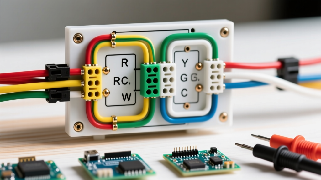
For fans utilizing remote controls (like the ubiquitous UC7080T or MR101Z receiver modules), the wiring diagram changes drastically. The receiver sits inside the ceiling canopy and acts as a solid-state relay.
The Failure Mode: The fan operates via remote, but the light flickers or dies completely.
The Diagnosis: The receiver module has failed on the lighting circuit. These modules handle the inductive load of the motor and the resistive load of the light kit. Over time, the triac governing the light circuit degrades, especially if the user has installed LED bulbs with incompatible built-in drivers that cause harmonic feedback.
The Fix: Bypass the receiver. If you want to convert a remote-controlled fan back to a standard hardwired fixture, follow the 'bypass' section of the wiring diagram. Connect the ceiling black wire directly to the fan black wire, and the ceiling red (or second black) directly to the fan blue wire. Cap off the receiver's white and blue output wires. A replacement UC7080T receiver costs between $18 and $28 in 2026, but bypassing it is a free, permanent fix if you don't mind using pull chains or smart bulbs.
Scenario 3: Smart Fans and the Disappearing Blue Wire
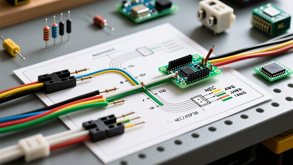
If you are troubleshooting a modern smart fan (such as the Modern Forms Wynd or Carro smart series), you will notice the wiring diagram lacks a distinct blue wire for the light kit. Instead, these 2025/2026 models utilize an integrated internal WiFi driver.
The ceiling canopy only requires three connections: Line (Black), Neutral (White), and Ground (Green). The internal microcontroller routes power to the DC motor and the LED light array via low-voltage DC wiring hidden inside the downrod. If the light fails on these models, the issue is rarely a wiring mismatch; it is almost always a failed internal LED driver board or a firmware desynchronization requiring a hard power-cycle at the breaker panel for 60 seconds.
NEC Compliance and Safety Clearances
While troubleshooting electrical faults, you must also verify mechanical and code compliance. According to the National Electrical Code (NEC), specifically Article 422.18, outlet boxes used for ceiling fan support must be listed and marked as acceptable for this purpose.
If you open the canopy to troubleshoot a wiring fault and find the electrical box is stamped with 'Not Suitable for Fan Support' or is a standard lightweight drywall box, you have identified a severe safety hazard. The vibration of the motor can loosen wire nuts over time, leading to arcing. The Electrical Safety Foundation International (ESFI) strongly recommends upgrading to a fan-rated brace box (like the Saf-T-Brace) capable of supporting up to 70 lbs before finalizing any wire connections.
Frequently Asked Troubleshooting Questions
Why does my ceiling fan light dim when the fan motor starts?
This indicates a voltage drop caused by a loose neutral connection or an undersized circuit. Check the white wire wire-nuts at both the ceiling box and the wall switch. If the connections are tight, the fan motor's start capacitor may be failing, drawing excessive amperage upon startup and starving the light kit of voltage.
Can I use a standard dimmer switch with the blue wire on my ceiling fan?
No. Standard incandescent dimmers will destroy the fan's light kit circuitry and may cause a fire hazard. If your wiring diagram for a ceiling fan with a light routes the blue wire to a wall switch, you must use a switch specifically rated for the type of bulbs installed (e.g., an LED-compatible ELV or TRIAC dimmer), or better yet, use a standard toggle switch and rely on the fan's internal remote dimming module.
My remote works, but the wall switch does nothing. What is wrong?
If the wall switch is turned 'OFF', it cuts power to the canopy receiver entirely. The remote cannot function without standby power. The wall switch must remain in the 'ON' position permanently to feed 120V to the receiver, allowing the remote's RF signals to trigger the internal relays.