
Decoding the Wiring Diagram for Electric Fan Circuits
Whether you are repairing a residential ceiling fan, an industrial exhaust blower, or a standalone pedestal fan, the underlying technology is almost always a single-phase AC induction motor. The most common variant in these applications is the Permanent Split Capacitor (PSC) motor. Locating and interpreting the correct wiring diagram electric fan manufacturers provide is the critical first step before applying power. Unlike three-phase industrial motors, single-phase fan motors require a phase shift to generate starting torque, which is achieved via a run capacitor and an auxiliary winding.
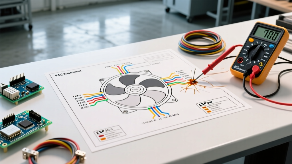
In this comprehensive motor wiring tutorial, we will break down the schematic symbols, standard wire color codes, and step-by-step procedures for wiring a PSC fan motor with a multi-speed selector switch. We will also cover real-world troubleshooting using a digital multimeter, ensuring you can diagnose open windings or failed capacitors safely and accurately.
The Physics of the Phase Shift
A single-phase power supply creates a pulsating magnetic field, not a rotating one. To make the fan rotor spin, the motor utilizes two distinct internal windings: the Main (Run) Winding and the Auxiliary (Start) Winding. The wiring diagram will always show a capacitor wired in series with the auxiliary winding. This capacitor shifts the electrical phase of the current flowing through the auxiliary winding by roughly 90 degrees, creating a rotating magnetic field that pulls the rotor into motion.
Standard Wire Color Codes in Fan Motors
While you should always defer to the specific schematic printed on the motor's nameplate, North American manufacturers like Regal Beloit (Fasco), Dayton, and Baldor generally adhere to a standardized color code for PSC fan motors. Understanding these colors allows you to map the physical wires to the wiring diagram electric fan schematics utilize.
| Wire Color | Function | Connection Point |
|---|---|---|
| Black | Main Winding (High Speed) | Speed Selector Switch / Line (L1) |
| Blue | Main Winding (Medium Speed) | Speed Selector Switch |
| Red | Main Winding (Low Speed) | Speed Selector Switch |
| White | Common / Main Winding Return | Neutral (L2) Line |
| Yellow / Brown | Auxiliary Winding | Run Capacitor (Terminal 1) |
| Brown with White Stripe | Auxiliary Winding Return | Run Capacitor (Terminal 2) |
Expert Note: Never connect the auxiliary winding wires directly to the AC line voltage. Bypassing the run capacitor will cause the auxiliary winding to draw excessive current and burn out within minutes, permanently destroying the motor.
Step-by-Step Motor Wiring Tutorial
Before beginning any electrical work, ensure the circuit breaker is turned off and locked out in accordance with NFPA 70 (National Electrical Code) safety standards. Verify the absence of voltage using a non-contact voltage tester.
Step 1: Verify Winding Resistance with a Multimeter
Before connecting the wires to the terminal block, verify the integrity of the internal windings. Set your digital multimeter to the Ohms (Ω) setting, typically the 200Ω range.
- Measure the Main Winding: Place one probe on the White (Common) wire and the other on the Black (High Speed) wire. A healthy 1/4 HP, 115V fan motor (such as the Fasco A173) will typically read between 15Ω and 25Ω.
- Measure the Auxiliary Winding: Place the probes on the Yellow and Brown wires. The resistance here is higher due to the thinner gauge wire used; expect a reading between 40Ω and 70Ω.
- Check for Ground Faults: Set the multimeter to the Megohm (MΩ) range or continuity. Place one probe on the White wire and the other on the unpainted metal casing of the motor. The reading must be infinite (OL). Any continuity indicates a short to ground, and the motor must be replaced.
Step 2: Wire the Run Capacitor
Most modern PSC fan motors require a 370VAC or 440VAC rated run capacitor, typically ranging from 1.5µF to 5µF depending on the motor's horsepower.
- Connect the Yellow wire to one terminal on the capacitor.
- Connect the Brown (or Brown/White) wire to the opposite terminal on the capacitor.
- Ensure the capacitor's metal casing is securely strapped to the motor housing or a grounded metal junction box to prevent vibration-induced wire fatigue.
Step 3: Connect the Speed Selector and Line Voltage
If your application uses a multi-speed rotary switch (like a Lutron or Hunter fan control), wire the speed taps as follows:
- Connect the Black, Blue, and Red wires to the corresponding High, Medium, and Low terminals on the speed switch.
- Connect the incoming AC Line (Hot) to the common input terminal of the speed switch.
- Connect the White (Common) wire directly to the incoming AC Neutral line. Use a properly sized wire nut (e.g., Ideal Yellow Wing-Nut for 14 AWG solid/stranded combinations) and torque to manufacturer specifications.
Troubleshooting Common Fan Motor Failures
Even with a perfect wiring diagram electric fan setups can fail due to environmental stress, capacitor degradation, or thermal overloads. Here is how to diagnose the most frequent issues:
Motor Hums but Will Not Spin
This is the hallmark of a failed run capacitor. Over time, the metallized film inside the capacitor degrades, dropping its microfarad (µF) rating. If a 5µF capacitor drops below 3.5µF, the phase shift is insufficient to generate starting torque. The Fix: Use a multimeter with a capacitance setting to test the capacitor. If the reading is more than 10% below the rated µF printed on the label, replace it with an identical voltage and capacitance rating. Premium brands like AmRad or Genteq 97F series cost between $8 and $15 and feature ruggedized dielectric oils.
Motor Runs for 10 Minutes, Then Shuts Off
This indicates the internal thermal overload protector (a bimetallic strip embedded in the winding) is tripping. Root Causes: 1. Restricted Airflow: Clogged HVAC filters or blocked exhaust louvers cause the motor to work harder, drawing higher amperage and generating excess heat. 2. Failing Bearings: If the rotor binds due to dried-out sleeve bearings, the mechanical load increases. Spin the shaft by hand (power off); if it does not spin freely for at least 3-4 seconds, the bearings are shot. Re-oiling is a temporary fix; replacement is recommended.
2026 Component Pricing and Sourcing Guide
When repairing commercial or high-end residential fan systems, sourcing OEM-equivalent parts is vital for longevity. Below is a current market breakdown for standard PSC motor components.
| Component | Specifications | Estimated Cost (2026) | Recommended Brands |
|---|---|---|---|
| Run Capacitor | 5µF, 440VAC, Round | $9.00 - $14.00 | AmRad, Genteq, Titan Pro |
| Replacement PSC Motor | 1/4 HP, 115V, 1075 RPM | $65.00 - $110.00 | Regal Beloit (Fasco), Dayton |
| Multi-Speed Fan Switch | 1.5 Amp, Rotary, 3-Speed | $12.00 - $22.00 | Lutron, Leviton |
| Motor Run Relay | 120V Coil, 10A Contacts | $15.00 - $25.00 | Omron, Schneider Electric |
Safety and Code Compliance
When wiring any motor circuit, adherence to the NEMA MG-1 standard for motor naming, sizing, and enclosure types is critical for commercial applications. Furthermore, the National Electrical Code (NEC) Article 430 dictates the requirements for motor circuit conductors and overload protection. For continuous duty fan motors, the branch circuit conductors must be sized to carry at least 125% of the motor's full-load ampere (FLA) rating as listed on the nameplate. Always ensure the motor's enclosure type (e.g., Open Drip-Proof (ODP) vs. Totally Enclosed Air Over (TEAO)) matches the environmental conditions of the installation site to prevent premature dielectric breakdown.
Frequently Asked Questions
Can I use a higher µF capacitor to make the fan spin faster?
No. While a slightly higher µF capacitor might marginally increase starting torque, it will cause the auxiliary winding to overheat and draw excessive current. Always replace a capacitor with the exact µF rating specified on the motor's wiring diagram, with a tolerance of +/- 5%.
Does it matter which way I wire the capacitor terminals?
For standard AC run capacitors, polarity does not matter. The terminals are interchangeable because alternating current reverses direction 60 times per second (in North America). However, if you are wiring a start capacitor with a bleed resistor, ensure the resistor is wired in parallel across the terminals.
Why does my fan motor have 5 wires instead of 3?
A 3-wire motor typically only offers a single speed. A 4-wire or 5-wire motor includes multiple taps on the main winding (Black, Blue, Red) to allow for multi-speed operation via an external switch or relay board, which is standard in modern HVAC air handlers and ceiling fans.
For further reading on optimizing motor efficiency and reducing electrical waste in HVAC systems, the U.S. Department of Energy's Motor Systems guide provides excellent data on upgrading from older shaded-pole fans to modern ECM (Electronically Commutated Motor) alternatives.