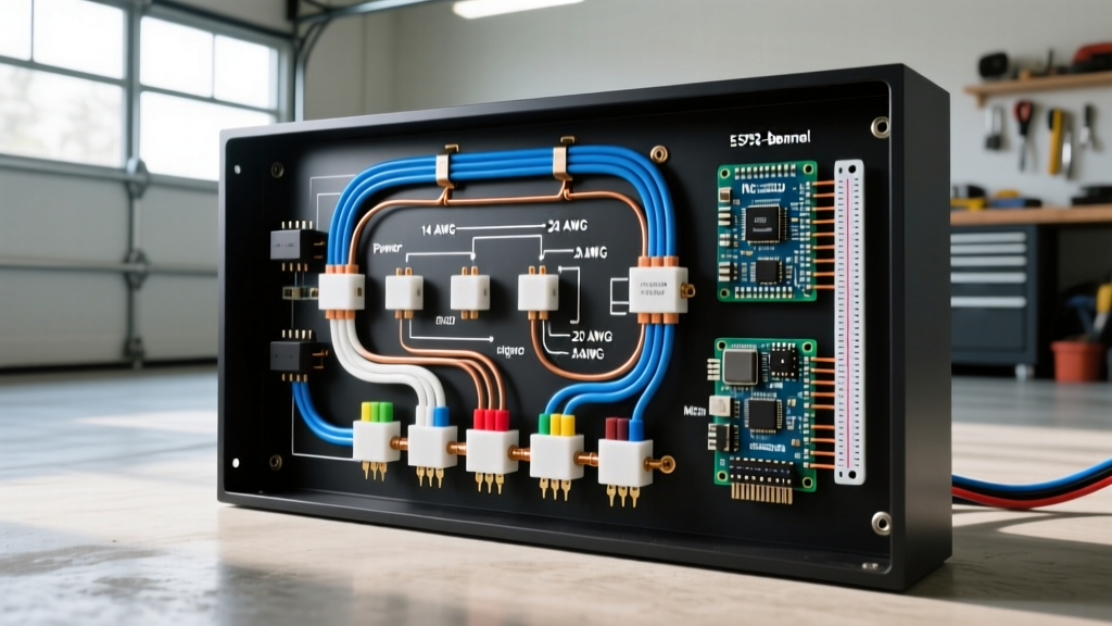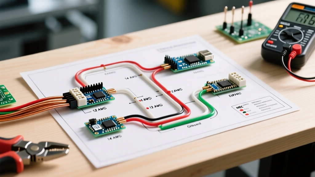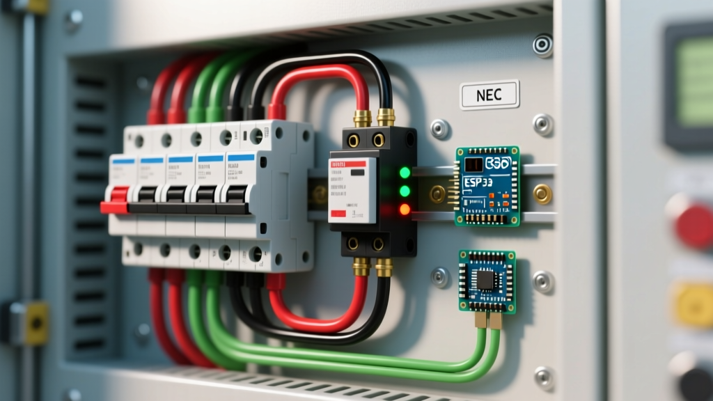

Integrating the Pressure Switch with Your Breaker Panel
When designing or upgrading a residential or agricultural water system, the pressure switch acts as the automated brain, but your main electrical panel provides the muscle. Understanding the correct wiring diagram for water pump pressure switch configurations is critical not just for operational reliability, but for meeting National Electrical Code (NEC) safety standards. A mismatch between the pump motor's Full Load Amps (FLA), the pressure switch contact rating, and the panel breaker size is one of the leading causes of premature motor failure and electrical fires in well systems.
As of 2026, with copper wire prices stabilizing but remaining a significant material cost, accurately calculating wire gauge and breaker sizing prevents both dangerous voltage drops and unnecessary material waste. This guide approaches the pressure switch from a 'Panel & Breaker' perspective, detailing how to properly size, route, and terminate the circuit from your main distribution board to the wellhead.
2-Wire vs. 3-Wire Submersible Pumps: How the Diagram Changes
Before pulling wire from your breaker panel, you must identify your pump type. The wiring diagram for water pump pressure switch setups diverges significantly based on the motor design:
- 2-Wire Pumps: The starting relay and capacitor are built inside the submersible motor housing. The circuit runs directly from the breaker panel to the pressure switch, and then straight down the well casing to the motor. The switch handles the full starting inrush current.
- 3-Wire Pumps: The starting components are housed in an above-ground control box. The pressure switch only controls the low-amperage relay coil inside the control box, while the heavy load current passes through the control box's contactor. Using a standard 2-wire diagram on a 3-wire system will instantly destroy the switch contacts.
For this guide, we will focus on the most common residential setup: the 2-wire, 230V, single-phase submersible pump paired with a standard Square D Pumptrol FSG2 or heavy-duty FYG32 pressure switch.
Breaker Sizing and Wire Gauge Matrix (NEC Article 430)
Sizing a breaker for a motor is fundamentally different from sizing one for a resistive load like a water heater. According to the National Fire Protection Association (NFPA 70), motor branch circuits must accommodate the massive Locked Rotor Amps (LRA) generated during startup without nuisance tripping, while still protecting the wire from short circuits.
NEC Article 430.52 allows the branch-circuit short-circuit and ground-fault protective device (the breaker) to be sized up to 250% of the motor's FLA for inverse-time breakers. Below is a practical reference matrix for standard residential well pumps:
| Motor HP | Voltage | Approx. FLA | Min. Copper Wire (75°C) | Max Standard Breaker Size |
|---|---|---|---|---|
| 1/2 HP | 230V | 5.0A | 14 AWG | 15A (2-Pole) |
| 3/4 HP | 230V | 6.9A | 12 AWG | 20A (2-Pole) |
| 1.0 HP | 230V | 8.0A | 12 AWG | 20A (2-Pole) |
| 1.5 HP | 230V | 10.6A | 10 AWG | 30A (2-Pole) |
| 2.0 HP | 230V | 12.0A | 10 AWG | 30A (2-Pole) |
| 3.0 HP | 230V | 17.0A | 8 AWG | 40A (2-Pole) |
Note: While 14 AWG is permitted for 1/2 HP motors by NEC ampacity tables, many local jurisdictions mandate a minimum of 12 AWG for all underground well feeders to mitigate voltage drop over long trench runs.
Step-by-Step: Wiring Diagram for Water Pump Pressure Switch
The standard Square D Pumptrol FSG2 (rated for 230V, up to 2HP) features four main terminal screws and a grounding lug. Here is the precise termination sequence from the panel to the pump.
1. Line Side Connections (From the Breaker Panel)
Run your 2-wire with ground (e.g., 10/2 UF-B or THWN-2 in PVC conduit) from the dedicated 2-pole breaker in your main panel to the pressure switch enclosure.
- Terminate the Black wire to the Line 1 (L1) terminal.
- Terminate the White wire (re-identified with black electrical tape or heat shrink at both ends to indicate it is a hot leg) to the Line 2 (L2) terminal.
2. Load Side Connections (To the Pump Motor)
Run your drop cable (typically a 3-conductor flat submersible pump cable with a green ground) from the switch down the well casing.
- Terminate the Black drop cable wire to the Motor 1 (M1) terminal.
- Terminate the Yellow drop cable wire to the Motor 2 (M2) terminal.
Pro-Tip: The contacts inside the FSG2 are directional. L1 must feed M1, and L2 must feed M2. Crossing the line and load sides can cause the switch to arc violently across the contacts when opening under load, leading to welded contacts and a pump that never shuts off.
3. Grounding and Bonding
NEC Article 250 requires strict equipment grounding for water systems due to the high conductivity of wet earth and water.
- Connect the Bare/Green ground wire from the breaker panel to the green grounding screw inside the metal pressure switch enclosure.
- Splice the panel ground to the Green drop cable ground wire using a waterproof, resin-filled wire nut or a copper crimp sleeve sealed with adhesive-lined heat shrink.
- Bond the metal well casing to the grounding electrode system at the wellhead.
Panel Integration: GFCI, AFCI, and Disconnect Rules
Integrating motor circuits into modern breaker panels often causes friction with updated NEC codes. Here is how to handle well pumps in 2026:
The GFCI Dilemma for Submersible Pumps
While the NEC heavily mandates Ground Fault Circuit Interrupter (GFCI) protection for outdoor receptacles, hardwired submersible well pumps are generally exempt from GFCI requirements unless specifically mandated by a local Authority Having Jurisdiction (AHJ). Deep well submersible motors naturally exhibit capacitive leakage to ground due to the hundreds of feet of cable submerged in water. Installing a standard 30mA GFCI breaker on a deep well circuit will almost always result in nuisance tripping, leaving the property without water. Use a standard HACR-rated inverse-time thermal-magnetic breaker.
Disconnecting Means (NEC 430.102)
If the pressure switch is located in the well pit or a detached pump house and the main breaker panel is not within sight (defined as within 50 feet and unobstructed), you must install a local disconnect switch. A 2-pole, 30A or 60A AC disconnect enclosure mounted adjacent to the pressure switch satisfies this code requirement, allowing maintenance workers to safely lock out the circuit.
Expert Insight: If your pump is rated at 2 HP or higher, or if your water system features a large bladder tank that causes rapid pressure oscillations, upgrade from the standard $25 FSG2 switch to the Schneider Electric FYG32 heavy-duty switch (approx. $75). The FYG32 features larger, silver-cadmium oxide contacts and an integrated unloader valve, drastically extending the lifecycle of the switch under high inductive loads.
Common Failure Modes and Troubleshooting
Even with a perfect wiring diagram for water pump pressure switch execution, environmental and electrical factors can cause system failures. Use this diagnostic framework when the breaker trips or the switch fails:
- Breaker Trips Instantly on Startup: This indicates a short circuit or a seized motor. Check for a melted drop cable spliced inside the well casing. Use a megohmmeter (megger) to test the insulation resistance of the drop cable; anything below 2 Megohms indicates water intrusion.
- Breaker Trips After 10-30 Seconds: This is a thermal overload trip. The motor is likely drawing high amps due to a failing bearing, sand lockage, or severe voltage drop. Measure the voltage at the pressure switch while the pump is running. If it drops below 207V (10% of 230V), you must upsize the feeder wire to compensate for the distance.
- Switch Contacts 'Chatter' or Weld Shut: If the FSG2 contacts pit and weld together, the pump will run continuously until the thermal overload in the motor destroys it. This happens when the switch is used to control a motor exceeding its HP rating, or when the system short-cycles (turns on and off more than 6 times per minute) due to a waterlogged bladder tank. Replace the switch and check the tank's pre-charge air pressure.
Summary Checklist for the Electrical Panel
Before energizing the circuit, verify the following:
- Breaker is sized correctly per NEC 430.52 (not exceeding 250% of FLA).
- Wire gauge is sufficient for both ampacity and a maximum 3% voltage drop over the total run length.
- White wire is properly re-identified as a hot conductor at the panel and the switch.
- Equipment grounding conductor is continuous and bonded to the switch enclosure and well casing.
- Pressure switch cover is secured, and all conduit knockouts are sealed with proper fittings to prevent moisture and insect intrusion.
For more detailed information on maintaining private water systems and protecting your wellhead infrastructure, consult the Penn State Extension Private Water Wells Guide. Proper integration of your pressure switch with your breaker panel ensures a safe, code-compliant, and reliable water supply for decades.