
Introduction to Chamberlain Motor and Logic Board Architecture
When approaching a wiring diagram for a Chamberlain garage door opener, the first critical realization for any electrician or advanced DIYer is the architectural shift that has occurred over the last decade. Older AC chain-drive models utilized simple line-voltage motor connections and mechanical limit switches. However, modern Chamberlain systems—such as the ultra-quiet B970T belt drive or the smart B2205T—utilize brushless DC motors integrated with a centralized logic board and a separate travel module.
From a motor wiring tutorial perspective, you are rarely wiring the motor stator directly. Instead, you are wiring the low-voltage control circuits, the travel module harness, and the safety sensors to the logic board, which then uses Pulse Width Modulation (PWM) to control the DC motor. Misinterpreting the wiring diagram can lead to fried logic boards, stripped travel gears, or catastrophic safety failures. This guide decodes the exact terminal layouts, wire gauge requirements, and diagnostic procedures for modern Chamberlain openers.
Decoding the Logic Board Terminals (The Core Diagram)
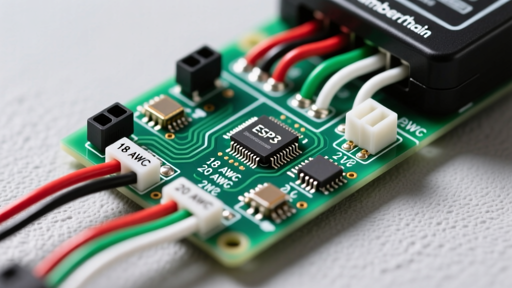
The heart of the Chamberlain wiring diagram is the low-voltage terminal block located on the back or side of the motor head logic board. Depending on the generation of your opener, the terminals will either be numbered (Legacy/Security+ 1.0) or color-coded (Security+ 2.0 / myQ enabled).
1. Safety Sensor Terminals (Red & White / Terminals 1 & 2)
The photoelectric safety sensors (sending and receiving eyes) operate on a 5V DC circuit provided by the logic board. On Security+ 2.0 boards, these connect to the Red and White terminals.
- Sending Sensor (Amber LED): Consumes roughly 45mA. Can be wired to either Red or White.
- Receiving Sensor (Green LED): Consumes roughly 45mA. The alignment indicator light will glow solid green only when it receives the infrared beam.
2. Wall Control Terminals (Red & White / Terminals 1 & 2)
Modern Chamberlain wall controls (like the 882LMW or 883LMW) do not use simple dry-contact switches. They use a data-over-power protocol. They share the Red and White terminals with the safety sensors. The logic board multiplexes the DC voltage, reading the unique digital handshake from the encrypted wall button. If you attempt to wire a standard dry-contact doorbell button to these terminals on a Security+ 2.0 board, the door will not operate, and you risk shorting the 5V logic rail.
3. Accessory and Travel Module Terminals
For models equipped with the PosiLock travel module (which replaces mechanical up/down limit switches), a dedicated multi-pin harness connects the module to the logic board. This is a proprietary plug-and-play connector; never attempt to splice or hardwire this harness, as it carries high-speed encoder data alongside 12V DC power.
Wire Gauge and Routing Specifications
Using the incorrect wire gauge is the leading cause of intermittent sensor failures and wall-control dropouts. Below is the definitive specification matrix for Chamberlain low-voltage circuits.
| Circuit Application | Recommended Wire Type | AWG Gauge | Maximum Run Length | Notes & Edge Cases |
|---|---|---|---|---|
| Safety Sensors | 2-Conductor Bell Wire | 22 AWG (Stranded) | 30 feet | If exceeding 30 ft, step up to 20 AWG to prevent voltage drop below 4.2V at the receiver. |
| Security+ 2.0 Wall Control | 2-Conductor Bell Wire | 22 AWG (Stranded) | 150 feet | Do not run parallel to 120V AC lines; maintain a 6-inch separation to avoid data packet corruption. |
| Keyless Entry (Outdoor) | 2-Conductor Bell Wire | 22 AWG (Stranded) | 100 feet | Ensure connections are sealed with dielectric grease to prevent copper oxidation. |
| 120V AC Power Supply | NM-B (Romex) or SJT Cord | 14 AWG (Solid/Stranded) | Branch Circuit Limit | Must be on a dedicated 15A or 20A GFCI-protected branch circuit per NEC guidelines. |
Step-by-Step Motor Wiring Tutorial: DC vs. AC Architectures
Understanding the difference between the motor wiring of an AC unit (e.g., C450 Chain Drive) and a DC unit (e.g., B970T Belt Drive) is crucial for replacements and upgrades.
AC Motor Wiring (Legacy & Standard Chain Drives)
- Stator Connection: The AC motor connects directly to the logic board via a heavy-gauge harness. The logic board uses internal relays to swap the polarity of the start winding, determining the direction of rotation.
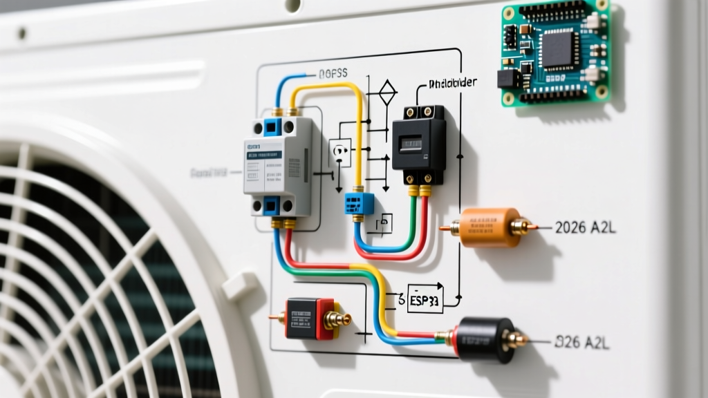
- Capacitor Circuit: A start/run capacitor is wired in series with the auxiliary winding. If the motor hums but does not turn, the wiring diagram points to the capacitor terminals. Test with a multimeter set to microfarads (µF); a variance of >10% from the rated spec indicates a failed capacitor, not a motor failure.
- Limit Switches: Mechanical limit switches are wired in series with the motor relays. Wiring these incorrectly will cause the door to run continuously and strip the drive gear.
DC Motor Wiring (Modern Belt & Premium Chain Drives)
- PWM Integration: The DC motor does not connect to line voltage. It connects to the logic board's motor driver IC via a specialized harness. The logic board varies the duty cycle of the DC voltage to provide soft-start and soft-stop functionality.
- Travel Module Encoder: The motor shaft is coupled to an optical or magnetic encoder. This encoder sends pulse trains back to the logic board to track the exact physical position of the door. If the encoder wiring harness is pinched or damaged during installation, the logic board will throw a Travel Module Error (usually 5 blinks on the diagnostic LED).
NEC & Safety Compliance Warning: According to the National Electrical Code (NFPA 70), all garage door opener receptacles must be readily accessible and GFCI protected. Furthermore, the Consumer Product Safety Commission (CPSC) mandates that photoelectric sensors must be installed no higher than 6 inches above the garage floor to prevent entrapment of small children or pets. Never bypass the sensor terminals to achieve a temporary fix.
Troubleshooting Wiring Faults & Edge Cases
When the physical wiring matches the diagram but the system fails, use the onboard diagnostic LED (located near the learn button) to isolate the fault. Here are the most common wiring-related error codes:
- 1 Flash (Sensor Wire Open): One or both sensor wires are broken or disconnected from the logic board. Test: Use a multimeter to check for continuity from the sensor pigtail to the logic board terminal.
- 2 Flashes (Sensor Wire Shorted): The Red and White wires are touching somewhere along the run, or a staple has pierced the insulation and shorted the conductors. Test: Disconnect wires at the board. If the LED stops flashing 2, the short is in the wall run, not the board.
- 3 Flashes (Wall Control Shorted / Incompatible): Often caused by wiring a non-Security+ 2.0 button to a modern board, or a short in the wall control data line.
- 4 Flashes (Sensor Misalignment / Voltage Drop): While usually an alignment issue, 4 flashes can also trigger if you used 24 AWG wire on a 40-foot run, causing the voltage at the receiving sensor to drop below the 4.5V threshold required to power the green LED and send the return signal.
Advanced Diagnostics: Multimeter Testing the Logic Board
Before replacing a suspected faulty logic board (which costs between $85 and $140 depending on the model), verify the board's output. Set your digital multimeter to DC Volts.
- Place the red probe on the Red sensor terminal and the black probe on the White sensor terminal.
- A healthy Security+ 2.0 logic board will output a pulsing DC voltage, typically averaging between 4.8V and 5.2V DC.
- If you read 0V, the board's internal 5V voltage regulator has failed, often due to a lightning strike or power surge entering through the sensor wires. In this case, the wiring diagram is intact, but the logic board requires replacement.
For comprehensive troubleshooting, always refer to the official Chamberlain product support documentation specific to your model's serial number, as terminal layouts can undergo minor revisions between manufacturing years. By respecting the wire gauge limits, understanding the shift to DC motor architectures, and properly terminating the Security+ 2.0 data lines, you ensure a safe, reliable, and code-compliant garage door installation.