
Mastering the Electric Motor Wiring Diagram 3 Phase Configurations
Three-phase induction motors are the undisputed workhorses of modern industrial, commercial, and heavy-duty residential applications. From driving 50-ton HVAC chillers to powering municipal water pumps, these machines rely on precise electrical connections to operate efficiently. However, misinterpreting an electric motor wiring diagram 3 phase schematic is one of the most common causes of catastrophic winding failure, breaker tripping, and costly downtime. In 2026, with the widespread adoption of IE4 and IE5 premium efficiency motors, the tolerances for wiring errors are lower than ever due to tighter magnetic air gaps and optimized thermal designs.
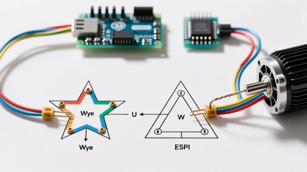
This comprehensive tutorial breaks down the physics, terminal configurations, and step-by-step wiring procedures for 3-phase motors, focusing heavily on the critical differences between Wye (Star) and Delta connections.
⚠️ CRITICAL SAFETY WARNING: Always perform Lockout/Tagout (LOTO) procedures per OSHA standards before opening any motor peckerhead (connection box). Verify zero energy state using a CAT III or CAT IV rated digital multimeter, such as the Fluke 87V, before touching any conductors.
Decoding the NEMA Nameplate
Before consulting any wiring diagram, you must understand the motor's nameplate. Governed by the NEMA MG-1 standard, the nameplate provides the exact electrical DNA of the machine. For dual-voltage motors (the most common type in North America), you will typically see a voltage rating like 230/460V. This indicates the motor can be wired for low-voltage (230V) or high-voltage (460V) operation, but the physical wiring configuration inside the peckerhead must change accordingly.
Key Nameplate Metrics for Wiring
- Full Load Amps (FLA): The current drawn at rated load and voltage. Crucial for sizing overload relays (typically set to 1.0 x FLA).
- Locked Rotor Amps (LRA) / Code Letter: Indicates the inrush current. A 'G' code letter means 5.6 to 6.29 kVA per horsepower during startup.
- Insulation Class: Usually Class F (155°C) or Class H (180°C) in modern motors. Dictates the maximum allowable temperature rise.
- Connection Type: Explicitly states if the internal windings are Wye (Y) or Delta (Δ).
9-Lead Dual Voltage Motors: Wye vs. Delta Matrix
Most standard 3-phase fractional and integral horsepower motors (up to 500 HP) utilize a 9-lead configuration. The way you group these nine leads (T1 through T9) determines whether the motor operates in a Wye (Star) or Delta configuration, and consequently, which voltage it accepts.
| Configuration | Voltage Applied | Terminal Jumper Connections | Power Lines (L1, L2, L3) |
|---|---|---|---|
| Delta (Low Voltage) | 230V | T1-T4-T7, T2-T5-T8, T3-T6-T9 | L1 to (1,4,7) L2 to (2,5,8) L3 to (3,6,9) |
| Wye (High Voltage) | 460V | T4-T7, T5-T8, T6-T9 (Tied together) | L1 to T1 L2 to T2 L3 to T3 |
Why the Voltage Difference?
In a Wye configuration, the windings are connected in a star pattern with a common neutral point (which is not brought out to the terminals). The voltage across each individual winding coil is the line voltage divided by the square root of 3 (approx. 1.732). Therefore, a 460V line voltage applies only 265V to each coil.
In a Delta configuration, the windings form a closed triangle. The full line voltage is applied directly across each coil. To keep the coil voltage at the safe 265V design limit when running on a 230V supply, the windings must be arranged in parallel Delta groups. If you accidentally wire a Wye motor for Delta on a 460V supply, you will apply 460V directly to coils designed for 265V, resulting in immediate insulation breakdown and a dead short.
Step-by-Step Termination Procedure
Proper termination goes beyond simply twisting wires together. According to guidelines from the National Electrical Code (NFPA 70), connections must be secure, properly torqued, and protected from environmental degradation.
- Prepare the Conductors: Strip exactly 5/8-inch of insulation from the supply wires. Do not nick the copper strands, as this creates a localized hot spot and reduces the wire's ampacity.
- Apply Anti-Oxidant (If Required): If transitioning from aluminum building wire to copper motor pigtails, apply a UL-listed anti-oxidant compound (like Noalox) to the aluminum strands to prevent galvanic corrosion.
- Use Proper Lugs or Nuts: For motors up to 10 HP, heavy-duty wire nuts (e.g., Ideal Wing-Nut) are acceptable. For 15 HP and above, use mechanical compression lugs or bolted terminal blocks. Never use electrical tape as a primary insulator inside the peckerhead.
- Apply Precise Torque: This is where most electricians fail. Use a calibrated torque screwdriver. For standard 1/4-inch terminal hardware, the target torque is typically 40 to 50 inch-pounds. Under-torquing causes arcing and heat; over-torquing strips the brass threads or cracks the terminal board.
- Dress the Wires: Carefully fold the connections back into the peckerhead. Ensure no bare copper is exposed and that the wires do not press against the sharp edges of the conduit knockout, which could slice the insulation during motor vibration.
Modern 2026 Considerations: VFDs and Inverter-Duty Motors
When wiring a 3-phase motor to a Variable Frequency Drive (VFD), the rules change slightly. Modern VFDs output a simulated 3-phase sine wave using Pulse Width Modulation (PWM). This creates high-frequency voltage spikes (dV/dt) that can destroy standard motor windings.
If you are wiring an inverter-duty motor to a VFD, you must use symmetrical shielded VFD cable (e.g., 3-conductor with 3 symmetrical ground wires). The shield must be terminated with a 360-degree EMC gland at both the VFD and the motor peckerhead to drain high-frequency capacitive currents safely to ground. Furthermore, for cable runs exceeding 50 feet, install a dV/dt filter or output reactor at the VFD to protect the motor's insulation system.
Critical Failure Modes and Edge Cases
Even with a perfect electric motor wiring diagram 3 phase reference, real-world conditions introduce edge cases that can destroy equipment.
1. Single-Phasing
If one of the three power lines drops out (due to a blown fuse or broken contactor), the motor will attempt to run on single-phase power. If it is already running, it will continue to spin but will draw up to 150% of its normal current in the remaining two phases. This causes rapid, asymmetrical heating. Without a phase-loss monitor or electronic overload relay, the windings will bake and fail within minutes.
2. Part-Winding Start Failures (12-Lead Motors)
Larger motors (often 12-lead) use a part-winding start to reduce inrush current. The motor starts on half the windings (Wye), and a timer engages the second half after 2 to 5 seconds. If the transition timer is set too long, the first half of the windings will overheat. If set too short, the mechanical jerk during transition can shear the motor shaft key or damage the driven load.
3. Megger Testing Mistakes
Before energizing a newly wired motor, perform an Insulation Resistance (IR) test. However, never megger test a motor while it is connected to a VFD or soft starter. The high DC voltage (usually 500V or 1000V DC) from the megger will instantly destroy the solid-state IGBTs in the drive. Always disconnect the motor leads from the drive before testing.
Frequently Asked Questions
Q: Can I run a 3-phase motor on single-phase residential power?
A: Not directly. You must use a rotary phase converter, a static phase converter, or a single-phase input / 3-phase output VFD. The VFD method is the most efficient and provides the best starting torque for 2026 residential workshop setups.
Q: How do I reverse the rotation of a 3-phase motor?
A: Rotation is determined by the phase sequence. To reverse the motor, simply swap any two of the three power leads (e.g., swap L1 and L2). Never swap the internal winding jumpers to change rotation.
Q: What is the difference between a Wye-Delta starter and a Wye-Delta motor?
A: A Wye-Delta motor has a specific internal winding design. A Wye-Delta starter is a reduced-voltage starting method used on standard 6-lead Delta motors, where the motor starts in a Wye configuration (reducing starting current to 33%) and transitions to Delta for running.
For further reading on motor efficiency standards and system optimization, refer to the Department of Energy's Advanced Manufacturing Office resources on premium efficiency motor selection.