
The Challenge of Single-Phase Motor Reversing
When you unbox a heavy-duty drum switch to control a single-phase AC motor and realize the paper insert is missing, faded, or entirely too generic, your immediate search for the wiring diagram for this switch often leads to conflicting forum advice. Unlike three-phase motors—where swapping any two legs instantly reverses rotation—single-phase capacitor-start motors require a precise rewiring of the internal windings to change direction. If you swap the wrong leads, the motor will run backward but lose up to 70% of its starting torque, overheat, and eventually trip its thermal overload.
In this 2026 motor wiring tutorial, we are breaking down the exact terminal mapping for the most common industrial DPDT (Double Pole, Double Throw) drum switches on the market, specifically the Dayton 5K386 and the Square D 2601. Whether you are wiring a Baldor L1406TM or a generic 1.5HP compressor motor, this guide provides the actionable specificity you need to wire safely and correctly.
CRITICAL SAFETY WARNING: Always adhere to OSHA Lockout/Tagout (LOTO) standards before opening any electrical enclosure. Verify zero voltage with a CAT III or CAT IV multimeter before touching terminals. Capacitor-start motors retain lethal charges in the run/start capacitors even when disconnected from line power.
Anatomy of a DPDT Drum Switch
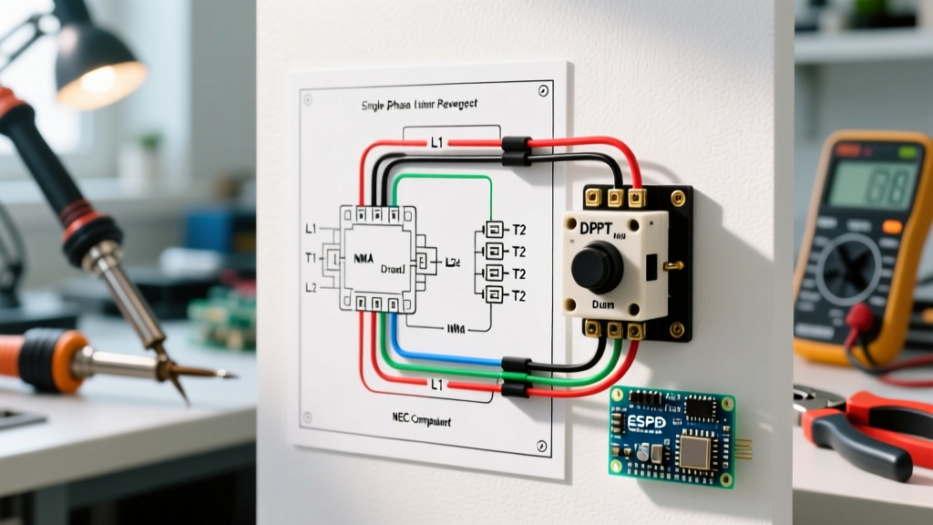
To understand the wiring diagram for this switch, you must first understand its internal architecture. A standard 6-terminal drum switch (like the Dayton 5K386, retailing around $75-$85 in 2026) or an 8-terminal variant (like the Square D 2601, currently $190-$240) utilizes a rotating cam mechanism to bridge specific terminals in the Forward, Off, and Reverse positions.
Why We Swap the Run Winding (Not the Start Winding)
A single-phase motor has two distinct internal circuits: the Start Winding (which provides the initial phase shift via a capacitor) and the Run Winding (which sustains rotation). To reverse the motor, you must reverse the polarity of the Run Winding relative to the Start Winding. If you mistakenly reverse the Start Winding instead, the motor will still reverse direction, but the centrifugal switch and capacitor circuit will be severely out of phase, leading to catastrophic winding failure under load.
Identifying Your NEMA Motor Leads
Before applying the wiring diagram for this switch, you must identify the leads coming out of your motor's peckerhead (connection box). The National Electrical Manufacturers Association (NEMA) standardizes these lead markings. Below is the standard identification matrix for a dual-voltage, capacitor-start, single-phase motor.
| Lead Marking | Winding Type | Function in Reversing Circuit |
|---|---|---|
| T1 & T4 | Main (Run) Winding | SWAP THESE: Polarity must be reversed relative to the line voltage to change rotation. |
| T5 & T8 | Start Winding | KEEP STATIC: These remain connected in parallel with the line, maintaining the same phase relationship. |
| T2 & T3 | Run Winding (Dual Voltage) | Used only for series/parallel voltage configuration (120V vs 240V). Tied together for 240V. |
| T6 & T7 | Start Winding (Dual Voltage) | Used only for series/parallel voltage configuration. Tied together for 240V. |
Note: If your motor only has 4 leads (typically labeled L1, L2, L3, L4 or simply unmarked colored wires), you must use an ohmmeter to identify the two separate winding pairs. The pair with the lower resistance (usually 1-3 ohms) is the Run Winding. The pair with higher resistance (usually 5-15 ohms) is the Start Winding.
Step-by-Step: Applying the Wiring Diagram for This Switch
The following steps apply to a standard 6-terminal DPDT drum switch configured for 120V or 240V single-phase operation. We will use 12 AWG THHN copper wire for a standard 20A motor circuit, which is the standard for most 1.5HP to 2HP single-phase motors in 2026.
Required Tools & Materials
- 12 AWG THHN stranded copper wire (Red, Black, White, Green)
- Wire strippers calibrated for 12-14 AWG (strip exactly 3/8 inch)
- Torque screwdriver (calibrated to 12-15 in-lbs)
- Ferrule crimpers and insulated ferrules (highly recommended for stranded wire in screw terminals)
The Terminal Mapping (6-Terminal Switch)
- Line Power In: Connect incoming Line 1 (Hot) to Terminal 1. Connect incoming Line 2 (Neutral or Hot 2) to Terminal 4.
- Motor Run Winding: Connect motor lead T1 to Terminal 2. Connect motor lead T4 to Terminal 5.
- Motor Start Winding: Connect motor lead T5 to Terminal 3. Connect motor lead T8 to Terminal 6.
- Grounding: Bond the motor chassis ground and the switch enclosure to the main Equipment Grounding Conductor (EGC) using a green grounding screw. Do not pass ground through the switch terminals.
How the Internal Cam Operates
- Forward Position: The switch bridges 1-to-2, 1-to-3, 4-to-5, and 4-to-6. Line 1 powers T1 and T5. Line 2 powers T4 and T8.
- Off Position: All bridges are broken. The motor is completely disconnected from line power, allowing it to coast to a stop.
- Reverse Position: The switch bridges 1-to-5, 1-to-6, 4-to-2, and 4-to-3. Line 1 now powers T4 and T8. Line 2 powers T1 and T5. The Run winding (T1/T4) has reversed polarity relative to the Start winding (T5/T8), reversing the motor shaft.
For a deeper dive into the physics of single-phase motor phase-shifting, the Electrical Technology motor reversing guide provides excellent oscilloscope waveform breakdowns of the start and run winding interactions.
Common Failure Modes & Troubleshooting Matrix
Even with the correct wiring diagram for this switch, operator error and mechanical stress can lead to specific failure modes. Below is a diagnostic matrix based on field service data from industrial maintenance technicians.
| Symptom | Probable Cause | Actionable Solution |
|---|---|---|
| Motor hums, trips breaker instantly in Reverse, but runs fine in Forward. | Start winding (T5/T8) and Run winding (T1/T4) leads were swapped at the switch terminals. | Verify NEMA lead markings. Swap the T1/T4 pair with the T5/T8 pair at the switch terminals. |
| Switch contacts welded together; motor will not turn off. | 'Plugging'—operator threw the switch from Forward directly to Reverse while the motor was still spinning at high RPM. | Replace the drum switch. Enforce a mandatory 'coast to zero' rule, or install a zero-speed plugging switch in the control circuit. |
| Motor runs hot and lacks torque under load in both directions. | Loose terminal connections causing voltage drop, or incorrect wire gauge (e.g., using 14 AWG on a 20A circuit). | Check torque on all terminals (12-15 in-lbs). Verify 12 AWG wire is used per NFPA 70 (NEC) Article 310. |
| Motor reverses direction randomly after thermal overload resets. | Centrifugal switch inside the motor is stuck closed, keeping the start winding energized and altering the magnetic field. | Disassemble motor peckerhead and inspect the centrifugal switch mechanism for carbon buildup or broken springs. |
NEC Code Compliance for 2026 Installations
When installing a manual drum switch for motor control, you must comply with the latest adoption of the National Electrical Code (NEC), specifically Article 430, which covers motors, motor circuits, and controllers.
Under NEC Article 430.83, a manual controller (like our DPDT drum switch) must be rated in horsepower (HP), not just amperage. If you are controlling a 2HP, 120V motor, the switch must carry a 2HP rating at 120V. Many cheaper toggle switches are rated only for 'resistive loads' (e.g., 20A resistive) but will fail catastrophically under the high inductive inrush current (Locked Rotor Amperage or LRA) of a motor startup, which can be 6 to 8 times the Full Load Amps (FLA). Always verify the HP rating stamped on the switch faceplate.
Frequently Asked Questions
Can I use a standard 3-position DPDT toggle switch instead of a drum switch?
Yes, but with severe limitations. A standard DPDT toggle switch (like a Carling or Bat-handle switch) usually lacks the internal bridging required to keep the start winding in parallel with the run winding across both polarities. You would need to manually wire complex external jumpers. Furthermore, standard toggle switches rarely carry an HP rating suitable for motors over 1HP. A dedicated drum switch is heavily spring-loaded to snap into position, minimizing the arc duration that destroys contacts.
What happens if I switch from Forward to Reverse without stopping?
This is known as 'plugging' or 'reverse-current braking.' The motor acts as a generator, and the sudden reversal of the magnetic field creates an inrush current that can exceed 150% of the normal Locked Rotor Amperage. In a manual drum switch, this massive arc will instantly melt the copper contacts, welding them together and creating a severe fire hazard. Always allow the motor to reach a complete stop before changing directions.
My motor only has 4 unmarked wires. How do I proceed?
You must isolate the windings using a digital multimeter. Measure the resistance between all wire combinations. You will find two pairs that show continuity. The pair with the lower resistance (e.g., 1.5 ohms) is your Run Winding. The pair with the higher resistance (e.g., 8.0 ohms) is your Start Winding. Label them T1/T4 and T5/T8 respectively, and proceed with the wiring diagram for this switch as outlined above.