
Strategic Planning for Hunter Ceiling Fan Installations
Jumping straight onto a ladder with a screwdriver and a wire stripper is the most common mistake DIYers make when installing a new ceiling fan. Modern ceiling fans, particularly those from industry leaders like Hunter, feature complex internal circuitry, integrated LED light engines, and optional smart-home receivers. Before you unbox your new fixture, locating and studying the wiring diagram for Hunter ceiling fan with light PDF specific to your model is a non-negotiable first step.
This installation planning guide is designed to help you decode Hunter's official PDF schematics, audit your existing electrical box, and select the correct wall controls. Whether you are installing a classic AC-motor Hunter Builder Elite (Model 53091) or a modern DC-motor Hunter Symphony with Wi-Fi capabilities, understanding the schematic before you touch a single wire will save you from blown breakers, fried receivers, and hours of troubleshooting.
Decoding the Hunter PDF Schematic: Core Wire Functions
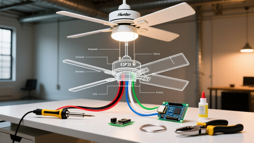
Hunter's official PDF wiring diagrams utilize a standardized color-coding system for the fan's internal leads. However, these colors often conflict with standard residential Romex wiring colors, leading to dangerous miswiring. Here is the master translation guide for the wires extending from the Hunter fan canopy:
- Black Wire: Fan motor power. Connects to the switched hot (usually black or red) from your ceiling.
- Blue Wire: Light kit power. Connects to a second switched hot if you have dual wall switches, or pigtailed with the black wire for single-switch operation.
- White Wire: Neutral return. Connects to the ceiling's white neutral bundle.
- Green/Copper Wire: Equipment ground. Must be bonded to the ceiling box ground and the supply ground.
Critical Safety Warning: Never connect the Hunter blue wire to the house's white neutral wire. Doing so will create a dead short the moment you flip the wall switch, instantly tripping the breaker and potentially damaging the fan's internal light limiter. Always verify power is off using a non-contact voltage tester like the Klein Tools NCVT-2 before beginning.
Pre-Installation Hardware & Electrical Box Audit
The PDF schematic assumes your ceiling box is properly rated for the dynamic load of a spinning fan. According to the National Electrical Code (NEC) Article 314.27(B), outlet boxes must be specifically listed for ceiling fan support if the fan exceeds 35 pounds. However, as a best practice in 2026, all ceiling fans should be mounted to fan-rated boxes to prevent long-term structural fatigue. Consult the CPSC Electrical Safety Guidelines for comprehensive home wiring safety standards.
| Box Type | Max Weight Limit | Best Application | NEC Fan Compliance |
|---|---|---|---|
| Standard Pancake (1/2 in) | 15 lbs | Ultra-light fixtures only | Fails for almost all Hunter fans |
| Retrofit Expandable Brace | 50 - 70 lbs | Existing drywall (no attic access) | Fully Compliant |
| Standard Joist-Mount (Fan Rated) | 35 - 50 lbs | Open attic / new construction | Fully Compliant |
| Heavy-Duty Steel Box | 70+ lbs | Hunter Original cast-iron models | Fully Compliant |
Note: The popular Hunter Dempsey (Model 59261) weighs approximately 22 lbs. While it technically falls under the 35 lb NEC threshold, the dynamic vibration requires a secure, fan-rated brace to prevent ceiling drywall cracking over time.
The Receiver Trap: Remote vs. Direct Wire Schematics
The most confusing aspect of any wiring diagram for Hunter ceiling fan with light PDF is the inclusion of the remote control receiver. Most modern Hunter fans (priced between $150 and $300) include a universal remote receiver module (such as the Hunter 99111) that sits inside the ceiling canopy.
Scenario A: Using the Included Remote Receiver
If you plan to use the remote, the PDF schematic changes entirely. You will not connect the house wires directly to the fan's black, blue, and white wires. Instead:
- Connect the house's constant hot (black) to the receiver's Black wire.
- Connect the house's neutral (white) to the receiver's White wire.
- Connect the receiver's Blue wire to the fan's Blue wire (light).
- Connect the receiver's Black (or sometimes Gray) output wire to the fan's Black wire (motor).
Failure Mode: If your wall switch is turned off, the remote receiver loses all power. You must bypass the wall switch or ensure it is permanently taped/locked in the "ON" position so the receiver maintains constant standby power.
Scenario B: Direct Wiring (No Remote)
If you prefer traditional dual wall switches and are discarding the remote receiver, follow the direct-wire section of the PDF. You will connect the house wires directly to the fan leads using UL-listed wire nuts (e.g., Ideal Industries 341 Blue or 314 Red). Ensure you strip exactly 1/2 inch to 5/8 inch of insulation from the solid copper house wires to ensure a secure bite inside the wire nut.
DC vs. AC Motors: A 2026 Wiring Paradigm Shift
Hunter's premium 2025 and 2026 lineup heavily features Energy Star certified DC (Direct Current) motors. According to ENERGY STAR Ceiling Fan Specifications, DC motors use up to 70% less energy than traditional AC motors. However, this introduces a massive wiring difference.
AC motor fans can be controlled by standard wall dimmers and fan speed controllers. DC motor fans cannot. The internal PCB (Printed Circuit Board) of a DC fan requires a constant 120V AC supply to power its internal rectifier. If you wire a Hunter DC fan to a standard wall dimmer, the fluctuating voltage will destroy the fan's internal logic board within minutes. When reviewing your PDF schematic, look for the "DC Motor" warning label. If present, you must use Hunter's proprietary wall control module or rely exclusively on the included RF remote.
Step-by-Step Execution Strategy
Once you have audited your box, selected your control method, and reviewed the PDF, follow this execution flow:
- Kill the Power: Turn off the 15A or 20A breaker at the main panel. Verify with a multimeter or NCVT.
- Install the Hanger Bracket: Secure the mounting bracket to the fan-rated box using the provided #10-32 or #12-24 machine screws. Do not use drywall screws.
- Assemble the Downrod: Thread the wires through the downrod, ensuring the internal set screws pierce the wire insulation slightly to prevent the rod from spinning. Insert the cotter pin and tighten the collar.
- Make the Electrical Connections: Using the PDF as your map, connect the grounds first, then neutrals, then hots. Give each wire nut a firm tug test.
- Seat the Canopy: Carefully tuck the wire nuts and receiver module into the electrical box. Align the canopy cover and secure the thumbscrews.
- Attach Blades and Light Kit: Mount the blade irons, attach the LED light housing, and plug in the internal Molex connector for the light kit.
Edge Cases & Troubleshooting Misinterpreted Diagrams
The "Missing Red Wire" Switched Loop
Many older homes (pre-1990) feature a "switched loop" at the ceiling, meaning you will only find a black, white, and bare copper wire in the ceiling box, with no red wire for separate light control. If your Hunter PDF shows a separate blue wire connection for the light, but you only have one hot wire available, you must pigtail the fan's black and blue wires together to the single house black wire. You will then rely on the fan's pull chains or remote to toggle between the fan and the light.
Smart Home Integration Failures
If you are attempting to integrate your Hunter fan with a smart home hub (like Lutron Caseta or Leviton Decora Smart), ensure you are purchasing a fan-speed smart switch, not a standard dimmer switch. Standard LED dimmers use phase-cut technology that will cause an AC fan motor to hum violently and overheat. For further technical support and to download model-specific PDF manuals, always refer to the official Hunter Fan Company Support portal.
Final Pre-Flight Checklist
Before restoring power at the breaker panel, perform a final visual audit. Ensure no bare copper ground wires are touching the white neutral wires. Verify that the remote receiver antenna wire (usually a thin black or white wire extending from the receiver module) is left loose and not bundled tightly inside a wire nut or wrapped around the metal canopy, as this will severely limit the RF signal range. Once verified, restore power, pair your remote according to the DIP switch settings outlined in the PDF, and test all six speed settings and light dimming functions.