
The Intersection of Comfort and Electrical Code Compliance
When homeowners and junior technicians look at a wiring diagram for furnace thermostat connections, they often dismiss the low-voltage control circuit as inherently safe. While the 24VAC control voltage itself poses minimal shock hazard, the circuits it commands—120V blower motors, 240V electric heating elements, and 120V/24V gas valve ignition sequences—carry lethal line voltages and significant fire risks if wired incorrectly. As of the 2026 NEC adoption cycle, improper low-voltage routing and undersized control transformers remain leading causes of residential HVAC electrical fires and control board failures.
This guide provides a comprehensive, code-compliant approach to reading and executing a furnace thermostat wiring diagram, emphasizing National Electrical Code (NEC) Article 725 requirements, proper wire gauge selection, and critical safety lockout procedures.
Decoding the Standard 24VAC Furnace Thermostat Wiring Diagram
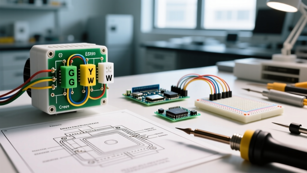
Modern forced-air gas and electric furnaces utilize a standardized 5-wire to 8-wire color-coded topology. The control board steps down 120VAC line voltage to 24VAC via an integrated Class 2 transformer. Below is the industry-standard terminal mapping you will encounter on universal control boards like the Honeywell ST9120U or OEM boards from Goodman and Trane.
| Terminal | Wire Color | Function & Code Context | Typical Load / Current Draw |
|---|---|---|---|
| R / Rc / Rh | Red | 24VAC Hot (Power from Transformer) | N/A (Source) |
| W / W1 | White | Stage 1 Heat (Gas Valve / Ignition Relay) | 0.5A - 1.2A |
| Y / Y1 | Yellow | Stage 1 Cooling (A/C Compressor Contactor) | 0.3A - 0.8A |
| G | Green | Indoor Blower Fan Relay | 0.2A - 0.5A |
| C | Blue/Black | 24VAC Common (Return Path) | N/A (Return) |
| W2 / Aux | Brown | Stage 2 / Auxiliary Heat (Electric Strips) | 0.5A - 1.0A |
Critical NEC Code Requirements for Thermostat Wiring
Thermostat wiring falls under NEC Article 725 (Class 1, Class 2, and Class 3 Remote-Control, Signaling, and Power-Limited Circuits). Ignoring these regulations is not just a code violation; it compromises the physical separation required to prevent line-voltage faults from energizing low-voltage components.
The 2-Inch Separation Rule (NEC 725.136)
Class 2 thermostat cables must be separated from Class 1 (line voltage) conductors by at least 2 inches (50mm) unless a physical, grounded barrier is installed between them. Never run 18 AWG thermostat wire inside the same conduit, junction box, or knock-out hole as 120V/240V Romex or THHN wire. If the low-voltage and line-voltage wires must cross, they must do so at a strict 90-degree angle to minimize electromagnetic interference (EMI) and prevent capacitive coupling.
Cable Rating and Fire Stopping
Only use UL-listed CL2 or CL3 rated cable for in-wall thermostat runs. Standard bell wire or unjacketed speaker wire lacks the fire-retardant PVC jacketing required to prevent flame propagation through wall cavities. When passing the thermostat cable through top plates or fire-blocking in finished walls, the hole must be sealed with fire-rated caulk or expanding foam to maintain the structural fire barrier.
Wire Gauge, Transformer Sizing, and Overcurrent Protection
A common failure mode in modern HVAC systems is the repeated blowing of the 3A purple ATO automotive blade fuse located on the furnace control board. This is almost always caused by undersized wiring, excessive cable runs causing voltage drop, or the installation of power-hungry smart thermostats without a dedicated Common (C) wire.
Sizing the Control Transformer and Wiring
- Standard Transformer: Most residential furnaces use a 40VA (Volt-Ampere) transformer. At 24VAC, this yields a maximum safe continuous current of 1.66 Amps (40VA ÷ 24V = 1.66A).
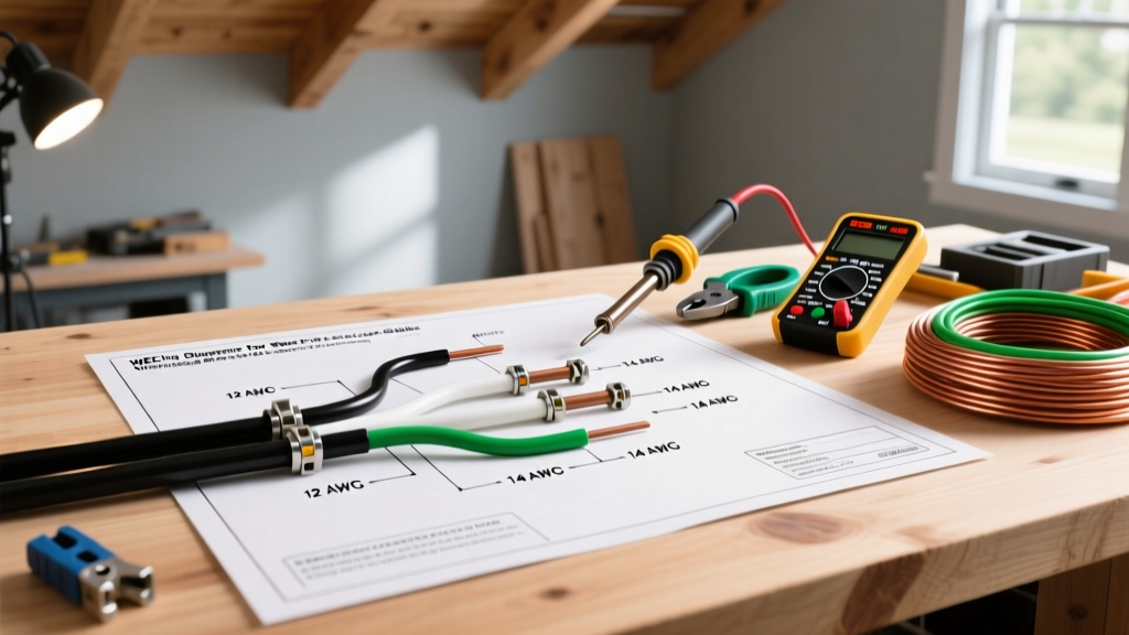
- Wire Gauge Selection: For runs under 50 feet, 18 AWG solid copper is mandatory. For runs between 50 and 100 feet, upgrade to 16 AWG to prevent voltage drop. If the voltage at the thermostat drops below 20VAC, smart thermostats like the Ecobee SmartThermostat Premium will reboot endlessly, and gas valve solenoids will chatter, eventually burning out the valve coils.
- The C-Wire Imperative: Modern Wi-Fi thermostats draw continuous power for screens and radios. 'Power stealing' (drawing current through the W or Y circuit while the equipment is off) is strongly discouraged and can violate UL listings for the control board. Always pull an 18/5 or 18/8 cable to ensure a dedicated C-wire is present.
Safety Warning: Before touching any thermostat wire, you must perform a Lockout/Tagout (LOTO) procedure on the main HVAC disconnect. As outlined by OSHA's Hazardous Energy Control standards, simply turning off the thermostat or the wall switch is insufficient. You must kill power at the 120V/240V service disconnect or breaker panel and verify zero energy with a CAT III multimeter.
Step-by-Step Safe Wiring Procedure
- Execute LOTO: Turn off the breaker feeding the air handler/furnace. Place a physical lock and tag on the panel. Verify 0V at the control board's L1 and L2 line-voltage terminals.
- Prepare the Cable: Strip back the outer PVC jacket of the 18/5 CL2 cable by exactly 1.5 inches. Strip the individual solid copper conductors by exactly 1/4 inch. Do not nick the copper, as this creates a stress fracture that will snap under thermal expansion cycles.
- Terminate at the Control Board: Loosen the terminal screws. Insert the bare wire straight into the terminal block—never wrap solid 18 AWG wire around the screw, as it can slip and short against adjacent terminals. Tighten to 'finger-tight plus a quarter turn' (approx. 4-5 in-lbs).
- Terminate at the Thermostat Base: Route wires through the baseplate. Ensure no bare copper is exposed outside the terminal block. A stray strand of the 'C' wire touching the 'R' wire will instantly blow the 3A control board fuse the moment power is restored.
- Continuity & Short Test: Before restoring power, use a multimeter in continuity mode. Place probes on R and C, then R and W, then R and Y. The meter should read 'OL' (Open Line). If it beeps, you have a dead short in the wall or at the terminals. Fix it before applying power.
Common Failure Modes and Code Violations Matrix
Troubleshooting a furnace that refuses to fire often comes down to analyzing how the thermostat wiring interacts with the control board's safety logic. According to the U.S. Department of Energy, improper HVAC controls account for significant energy waste and component degradation.
| Symptom | Probable Wiring Fault | Code / Safety Implication |
|---|---|---|
| 3A Control Board Fuse Blows Instantly | Short between R and C, or R and G. Bare copper strands touching at terminal block. | Fire hazard if undersized wire is used; transformer overheating. |
| Smart Thermostat Reboots Continuously | Missing C-wire; voltage drop below 20VAC due to 20 AWG wire or >75ft run. | Violates manufacturer UL installation instructions; causes relay chatter. |
| Blower Runs, But No Heat/Cool | G wire shorted to R or W. Thermostat internal relay failure. | Potential freeze damage to AC coils if Y and G cross. |
| Thermostat Screen Shock / Tingling | Line voltage (120V) bleeding into Class 2 circuit via damaged insulation in the wall. | Severe NEC 725.136 violation. Immediate shock and fire hazard. |
FAQ: Furnace Thermostat Wiring Compliance
Can I use standard 18 AWG speaker wire instead of CL2 thermostat wire?
No. Speaker wire lacks the CL2 (Class 2) fire-retardant jacketing required by the NEC for in-wall installation. In the event of a short circuit that causes the wire to overheat, standard speaker wire will ignite and propagate flame through the wall cavity, whereas CL2 wire is designed to self-extinguish.
Is it legal to wire a 24VAC thermostat circuit to a smart home relay module?
Yes, provided the relay module is UL-listed for HVAC control and the wiring adheres to NEC Article 725. However, you must ensure the combined VA draw of the thermostat, the smart relay, and the furnace contactor coils does not exceed 80% of the control transformer's rated capacity (e.g., 32VA on a 40VA transformer). If it does, you must upgrade to a 50VA or 75VA transformer and upgrade the control board fuse to match the new transformer's primary/secondary protection limits.
What happens if I swap the R and C wires at the thermostat?
While 24VAC is alternating current and technically has no fixed 'polarity,' modern HVAC control boards and smart thermostats utilize half-wave rectification and specific grounding references. Swapping R and C can bypass internal protection diodes, instantly destroying the thermostat's internal logic board and potentially sending 24VAC back through the common bus, which can fry the microprocessor on the furnace control board. Always follow the exact wiring diagram for furnace thermostat layouts provided by the manufacturer.