
The Dual Nature of Double Wide Electrical Systems
When evaluating a wiring diagram for double wide mobile home configurations, electricians and DIYers must understand that these structures exist in two distinct phases: the vehicle transit phase and the permanent dwelling phase. Unlike site-built homes, a double wide is manufactured in two separate chassis units, transported on highways, and joined on-site. This means the electrical schematic must account for temporary Department of Transportation (DOT) transit wiring, as well as the critical 'marriage wall' splice that unifies the two halves into a single 200-amp NEC-compliant dwelling.
CRITICAL SAFETY WARNING: Never attempt to splice the marriage wall junction boxes while the main exterior disconnect is energized. Double wides are notorious for shared neutrals and mislabeled multi-wire branch circuits (MWBCs) crossing the center seam. Always lock out the 200A main feed before opening the center-line junction boxes.
HUD Code vs. NEC: What Governs Your Wiring Diagram?
Before tracing any wires, you must know which code applies to the section of the home you are working on. The factory-installed wiring is governed by the HUD Manufactured Home Construction and Safety Standards (24 CFR Part 3280). However, once the home leaves the factory and is installed on a permanent foundation, the site-side wiring and the final connection to the utility grid fall under NFPA 70: National Electrical Code (NEC) Article 550.
- Factory Wiring (HUD): Uses specific Romex (NM-B) routing, requires ground fault protection in wet areas, and mandates the use of listed junction boxes for the marriage wall.
- Site Wiring (NEC Art. 550): Governs the service mast, the exterior disconnect, the underground feeder trench, and the grounding electrode system (ground rods and water pipe bonding).
Core Wiring Diagram: The 200-Amp Service Entrance
Modern double wides (built post-2010) almost universally require a 200-amp, 4-wire service. The standard wiring diagram routes power from the utility pedestal to an exterior disconnect, then into the home's main distribution panel.
Component Specifications & Pricing (2026 Estimates)
- Exterior Disconnect: Square D HOM200CP (200A, NEMA 3R). Cost: ~$145. Must be located within sight of the home.
- Feeder Cable: 4/0-4/0-2/0-6 AWG Aluminum URD (Underground Residential Distribution) direct burial cable. Cost: ~$5.50 per foot. Requires a 24-inch deep trench with warning tape.
- Interior Main Panel: Eaton BR200 or Square D HOM40M200PC (40 spaces, 80 circuits). Cost: ~$185. Located on an exterior wall or the marriage wall, never in a bathroom or closet.
The diagram dictates that the neutral and ground must be bonded only at the exterior disconnect (the first point of disconnect). Inside the home's main panel, the neutral bar must be isolated from the ground bar, with a separate 4 AWG bare copper bonding jumper connecting the ground bar to the panel enclosure.
The Marriage Wall Splice: Unifying the Two Halves
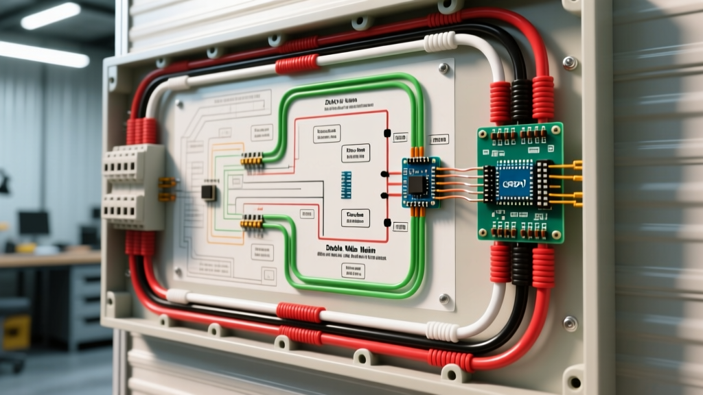
The most complex part of any double wide wiring diagram is the marriage wall splice. When the two halves of the home are pushed together on the chassis, the electrical circuits must be mated.
Evolution of the Splice Connector
In older models (1980s-1990s), manufacturers used 50-pin Amp/Tyco multi-pin plastic connectors. These are notorious for pin corrosion, loose seating, and voltage drops. If your diagram shows a multi-pin plug, it is highly recommended to bypass it.
Modern diagrams utilize hardwired junction boxes mounted on the top plate of the marriage wall. The preferred method for splicing the main 100A or 125A sub-feeds that cross the marriage wall is using Polaris Insulated Submersible Splice (ISR) connectors. Specifically, the Polaris ISR-4/0 handles up to 4/0 AWG wire, requires no tape, and provides a watertight, vibration-proof seal. At roughly $18 per connector, they are vastly superior to traditional split-bolt connectors wrapped in friction tape.
Step-by-Step Marriage Wall Hardwiring
- Identify the master junction box (usually located in the attic space or behind a removable access panel on the ceiling of the center hallway).
- Strip 1-1/4 inches of insulation from the NM-B cables crossing the seam.
- Use Wago 221 series lever nuts for 12 AWG and 14 AWG lighting/receptacle circuits crossing the wall. These allow for easy future troubleshooting.
- For the 240V HVAC lines crossing the seam, use 30A rated ceramic terminal blocks or Polaris connectors to prevent arcing under heavy compressor startup loads.
Appliance Circuit Matrix & Wire Gauge Guide
Because double wides have restricted floor joist cavities (often only 8 to 10 inches deep), wire routing is tight. Heat dissipation is a concern, making proper wire gauge selection critical. Below is the standard wiring matrix for a 200A double wide setup.
| Appliance / Circuit | Breaker Size | Wire Gauge (Copper) | Wire Gauge (Aluminum) | HUD/NEC Notes |
|---|---|---|---|---|
| Electric Range/Oven | 50A (2-Pole) | 6 AWG | 4 AWG | 4-wire receptacle (NEMA 14-50R) required. No 3-wire retrofits. |
| Electric Water Heater | 30A (2-Pole) | 10 AWG | 8 AWG | Must be on a dedicated circuit. No shared neutrals. |
| Central HVAC (Heat Pump) | 40A (2-Pole) | 8 AWG | 6 AWG | Requires exterior disconnect within sight of condenser. |
| General Lighting | 15A (1-Pole) | 14 AWG | 12 AWG | AFCI protection required at the panel for bedroom circuits. |
| Kitchen Countertop | 20A (1-Pole) | 12 AWG | 10 AWG | Minimum two 20A small-appliance branch circuits required. |
The Vehicle Phase: Transit Wiring & DOT Compliance
Viewing the double wide through a 'vehicle-specific' lens reveals a secondary, temporary wiring harness. During highway transport, the home requires functioning tail lights, brake lights, and turn signals. Manufacturers install a temporary 12V DC wiring harness routed along the steel I-beam chassis.
This harness is powered by a standard 7-way RV blade connector at the front hitch. Once the home is set on its concrete piers and the axles are removed, this 12V transit harness is completely disconnected. Do not attempt to integrate this 12V transit harness into the home's permanent 120/240V AC lighting system. Doing so is a severe code violation and a fire hazard. The transit harness should be coiled, capped, and secured inside the belly wrap for future relocation if necessary.
Common Failure Modes in Pre-Owned Double Wides
When troubleshooting an existing wiring diagram in an older double wide, look out for these specific edge cases:
- The 'Floating' Marriage Wall Neutral: If half the home has dimming lights while the other half has over-voltage (bright lights, blowing bulbs), the main neutral splice at the marriage wall has failed. This causes the 240V feed to split unevenly across the two 120V legs based on the load imbalance. Fix immediately to prevent appliance fires.
- Belly Wrap Condensation Corrosion: NM-B (Romex) cable run through the floor joists is exposed to moisture if the polyethylene belly wrap is torn by rodents. This leads to blackened, corroded copper at the first-floor receptacles.
- Improper Grounding Electrodes: Many installers fail to drive two 8-foot copper ground rods at the site. According to NEC 250.53(A)(2), if a single rod has a resistance to ground greater than 25 ohms, a second rod must be driven at least 6 feet away.
Frequently Asked Questions
Can I use a 100-amp panel for a modern double wide?
While technically possible for very small, all-gas double wides under 1,000 square feet, it is highly discouraged. Modern electric HVAC systems, water heaters, and kitchen appliances will easily max out a 100A service. A 200A panel (like the Square D HOM40M200PC) is the industry standard and costs less than $50 more than a 100A panel, saving you a costly future upgrade.
Where should the main breaker be located?
Under NEC Article 550.32(B), the main disconnecting means must be located outdoors, within sight of the manufactured home, and at least 30 inches above the finished grade. It cannot be located inside the home's interior panel unless that interior panel is immediately adjacent to the point of entry and the exterior feed is fully protected.
Are multi-pin marriage wall connectors safe to keep?
If your home was built before 2005 and uses a plastic multi-pin plug at the marriage wall, it is safe only if the pins are clean, tight, and free of thermal scorching. However, best practice during a renovation or re-leveling is to cut out the multi-pin plug and hardwire the junction box using Wago lever nuts and Polaris lugs for a permanent, maintenance-free connection.