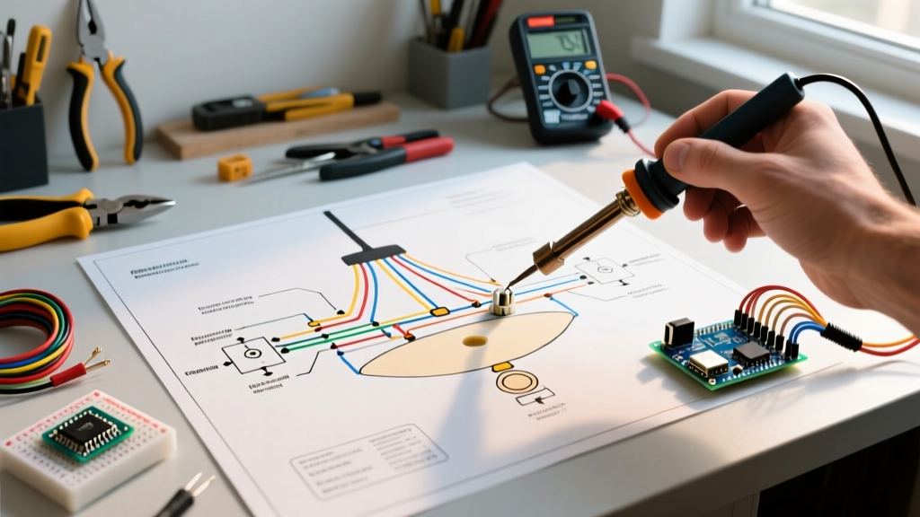

Why Chandeliers Fail: The Intersection of Vibration and Voltage
Chandeliers are unique in the electrical landscape. Unlike a standard flush-mount ceiling fixture, a multi-tier chandelier introduces mechanical stress, thermal cycling, and complex wire routing into a single assembly. When a $600 Kichler or Restoration Hardware fixture starts flickering, dropping bulbs, or emitting a faint buzzing sound, the issue is rarely the bulbs themselves. More often than not, the fault lies hidden inside the canopy or the central downrod. To diagnose these issues safely and efficiently, you must understand how to read and apply a wiring diagram for chandelier fixtures.
As of 2026, modern LED drivers and smart home relays have added layers of complexity to traditional lighting circuits. A standard 14/2 or 12/2 Romex branch circuit meets the fixture at the canopy, where it transitions to 18 AWG stranded TFN/TFFN fixture wire. This transition point is where 90% of chandelier failures originate. In this guide, we will break down the schematic, trace common failure modes, and provide a definitive troubleshooting matrix to get your fixture running perfectly.
Decoding the Wiring Diagram for Chandelier Setups
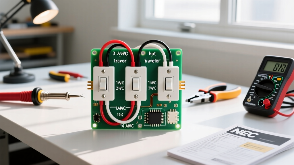
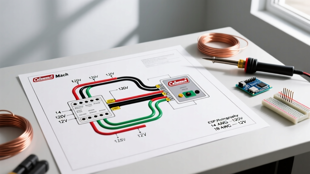
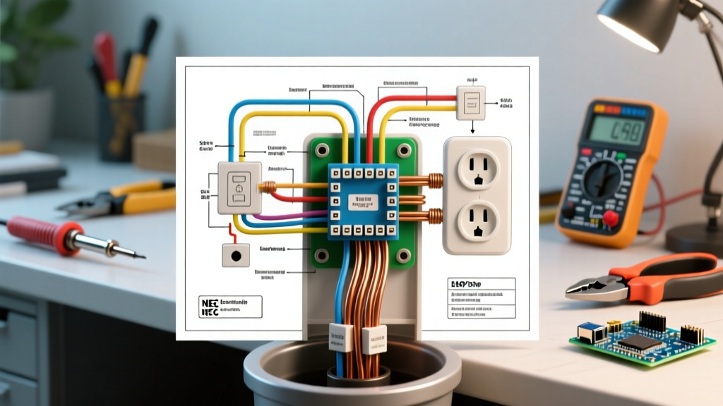
Before touching a screwdriver, you need to visualize the circuit. A standard residential chandelier wiring diagram consists of four primary conductors:
- Line (Hot): Typically black (or red in a 3-way switch loop). Carries 120V AC from the breaker panel.
- Neutral: White conductor. Completes the circuit back to the panel. Crucial for smart switches and LED drivers.
- Ground: Bare copper or green. Bonds the metal chassis of the chandelier to the home's grounding electrode system to prevent shock hazards.
- Switch Leg (Load): The wire returning from the wall switch to the canopy, interrupting the Line voltage.
When examining the manufacturer's schematic, look for the canopy splice block. In multi-light chandeliers, the internal 18 AWG wires from individual bulb sockets are bundled together in parallel. The diagram will show all socket neutrals twisted together and pigtailed to the branch circuit neutral, while the socket hots are bundled and connected to the switch leg. If your diagram shows a 3-wire setup (Line, Neutral, Ground) but your ceiling box only has a 2-wire switch loop (an older home configuration), you will immediately identify why a smart dimmer or Wi-Fi relay is failing to power on.
The Canopy Splice: Where Heat and Vibration Collide
The canopy is a hostile environment for electrical connections. It traps heat rising from the bulbs and is subject to micro-vibrations every time a door slams in the house or heavy footsteps occur on the floor above. Over time, these vibrations can back out standard twist-on wire nuts, creating high-resistance connections that lead to arcing and flickering.
Upgrading to Lever Connectors
When your wiring diagram for chandelier repair indicates a canopy splice failure, discard the cheap plastic wire nuts. Replace them with Wago 221-413 lever connectors (approximately $0.65 each). These lever-nuts provide a gas-tight, vibration-proof connection between the solid 14 AWG branch wire and the stranded 18 AWG fixture wire. Furthermore, they allow you to easily probe the connection with a multimeter without dismantling the splice.
Troubleshooting Matrix: Symptoms, Diagram Checks, and Fixes
Use the following matrix to cross-reference your physical symptoms with the wiring diagram and multimeter readings. For voltage testing, we recommend a True-RMS meter like the Fluke 117 (~$210) to ensure accurate readings on non-linear LED loads.
| Symptom | Diagram Check Point | Multimeter Test (Canopy) | Actionable Fix |
|---|---|---|---|
| Half the bulbs are dead; others work fine. | Parallel neutral splice inside the central downrod. | Test continuity from dead socket neutral to canopy neutral bundle. Expect OL (Open Line). | Open the downrod, locate the broken 18 AWG neutral wire, and solder/splice with a micro Wago connector. |
| LEDs flicker wildly when dimmed below 40%. | Dimmer switch wiring (Line vs. Load) and dimmer type. | Measure AC voltage at the socket under load. Look for erratic phase-cut waveforms. | Replace old TRIAC dimmer with an LED-compatible ELV/MLV dimmer (e.g., Lutron Diva DVCL-153P, ~$32). |
| Faint buzzing from the canopy, no light output. | Smart relay or Wi-Fi module power supply. | Measure voltage across Line and Neutral at the canopy. Should be a steady 120V AC. | Ensure the smart relay has a dedicated neutral connection. Check for a failed internal LED driver capacitor. |
| Breaker trips immediately upon switching on. | Ground fault in the metal chassis or pinched wire in the chain. | Test continuity between the Hot wire and the bare Ground wire. Expect OL. If low resistance, fault exists. | Inspect the chain links for pinched fixture wire. Apply heat-shrink tubing to exposed stranded wire near the canopy loop. |
Deep Dive: Dimmer Incompatibility and Phase-Cut Waveforms
The most common reason homeowners search for a wiring diagram for chandelier troubleshooting is LED flickering on a dimmer. Older chandeliers used incandescent bulbs, which are purely resistive loads. They work perfectly with leading-edge TRIAC dimmers. Modern LED chandeliers, however, use internal drivers that present a capacitive or inductive load to the circuit.
If your diagram shows that the chandelier uses low-voltage halogen or integrated LED modules powered by an electronic transformer, you must use a Trailing-Edge (ELV) dimmer. Wiring a standard leading-edge dimmer to an ELV driver will cause the driver to overheat, buzz, and eventually fail. Always verify the dimmer's wiring diagram to ensure the blue wire (usually the ELV load wire) is connected to the fixture's hot, rather than the black wire (forward phase).
Advanced Troubleshooting: Smart Relays and 3-Way Loops
Integrating a large chandelier into a smart home system often requires hiding a relay (like the Shelly 1 or Lutron Caseta dimmer) inside the canopy. This is where the wiring diagram becomes critical.
- Verify the Neutral: Most smart relays require a neutral wire to power their internal Wi-Fi/Zigbee radios. If your ceiling box only has a Line, Load, and Ground (a classic switch loop), you cannot install a standard smart relay in the canopy without pulling a new 14/3 cable from the switch to the ceiling.
- Space Constraints: A Shelly Plus 1Mini is roughly 1.5 x 1.5 inches. Before purchasing, measure the depth of your chandelier canopy. Many decorative canopies are too shallow to house both the wire splices and a smart relay. In these cases, the relay must be installed in the wall switch box, not the canopy.
Essential Tools for Safe Chandelier Diagnostics
Working overhead with heavy fixtures requires strict adherence to electrical safety protocols. According to the Occupational Safety and Health Administration (OSHA), verifying the absence of voltage is a mandatory step before touching any conductor. Never rely solely on the wall switch being in the "off" position.
- Non-Contact Voltage Tester: The Klein Tools NCVT-3 (~$35) detects both standard 120V and low-voltage 12-48V signals, making it ideal for checking both branch circuits and low-voltage chandelier transformers.
- Fiberglass Step Ladder: Never use an aluminum ladder when troubleshooting live circuits overhead. A 6-foot fiberglass Werner ladder provides the necessary dielectric protection.
- Chandelier Support Hook: When dropping the canopy to inspect the wiring diagram and splices, the fixture's weight will hang entirely on the thin 18 AWG wires if not supported. Use a specialized ceiling hook or a bent wire coat hanger to support the chain and take the mechanical strain off the electrical connections.
Expert Insight: When reassembling the canopy, ensure the ground wire is bonded not just to the ceiling box, but also to the chandelier's central threaded nipple. According to the National Electrical Code (NEC) Article 410, exposed metal parts of lighting fixtures must be grounded. A loose locknut on the threaded nipple can leave the entire metal frame of the chandelier energized in the event of an internal short circuit. Always use a grounding screw with a green pigtail to bond the nipple directly to the branch circuit ground.
Final Verification and Load Testing
Once you have traced the wiring diagram, repaired the canopy splices, and verified the dimmer compatibility, perform a full load test. Turn the breaker back on and energize the chandelier. Use an infrared thermometer to scan the canopy and the wall dimmer switch after 15 minutes of continuous operation. The canopy should remain near ambient room temperature. If the dimmer switch faceplate exceeds 120°F (49°C), you have likely exceeded the dimmer's maximum LED load rating, and you must upgrade to a higher-capacity commercial dimmer or reduce the number of bulbs in the fixture.
By systematically following the schematic and understanding the transition between branch circuit wiring and fixture wiring, you can eliminate the guesswork from chandelier repair. For more comprehensive guides on residential lighting circuits and NEC compliance, refer to the National Fire Protection Association's NEC resources and the Department of Energy's lighting efficiency guidelines.