
The Anatomy of a Multi-Light 3-Way Circuit
Troubleshooting residential lighting requires more than just swapping out a faulty toggle; it demands a fundamental understanding of circuit topology. When you are dealing with a wiring diagram for a three way switch with multiple lights, the complexity increases exponentially compared to a single-pole setup. You are no longer just breaking a single hot wire. Instead, you are managing a continuous hot feed, two traveler wires, a load feed, and a daisy-chained series of lighting fixtures.
In a standard 2026 residential build or retrofit, this circuit typically utilizes 14 AWG copper wire (for 15-amp breakers) or 12 AWG copper wire (for 20-amp breakers). The most common topology routes the line voltage (power from the panel) into Switch A. From Switch A, a 14/3 or 12/3 cable carries the two traveler wires and a neutral to Switch B. Finally, a 14/2 or 12/2 cable runs from Switch B to the first light fixture, with subsequent 14/2 cables daisy-chaining to the remaining lights.
Reading the Wiring Diagram for a Three Way Switch with Multiple Lights
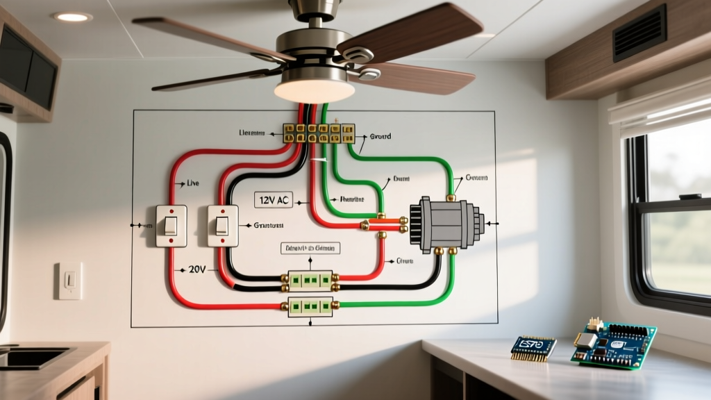
Before touching a wire nut, you must visually map the physical wiring to the schematic. The diagram hinges on three critical nodes:
- The Common Terminal (Line/Load): Usually identified by a black or dark-colored screw on standard switches like the Leviton Decora 5603-2W. On Switch A, this connects to the incoming hot. On Switch B, this connects to the outgoing load feeding the lights.
- The Traveler Terminals: Identified by brass-colored screws. These two wires (often red and black in a Romex 14/3 cable) carry the alternating hot current between the switches depending on the toggle positions.
- The Neutral Bundle: White wires that bypass the switches entirely (in legacy setups) or connect to the switch (in modern smart switch setups) to complete the 120V circuit back to the panel.
The Daisy-Chain Topology at the Fixtures
At the first light fixture, the diagram shows the incoming switched hot (from Switch B) connecting to the black lead of the light, while the white neutral connects to the silver lead. Crucially, the diagram also shows a second set of black and white wires branching off to the second light. If the first light works but the second does not, your fault lies in the wire nuts connecting the feed-through at the first fixture's junction box.
Diagnostic Matrix: Symptoms vs. Diagram Nodes
When a homeowner reports that the hallway or staircase lights are malfunctioning, use this diagnostic matrix to isolate the fault using your wiring diagram as a map.
| Symptom | Probable Cause | Diagram Node to Check | Multimeter Test Required |
|---|---|---|---|
| Lights work from Switch A, but Switch B does nothing. | One traveler wire is disconnected or broken. | Traveler Terminals (Brass screws) | Continuity test on red/black wires between boxes. |
| Lights work only when both switches are in the 'UP' position. | Common terminal miswired as a traveler on one switch. | Common Terminal (Black screw) | Voltage test (Line to Ground) on the black screw. |
| All lights completely dead regardless of switch position. | Tripped breaker, broken line feed, or open neutral at fixture 1. | Line Feed / Neutral Bundle | Voltage test (Line to Neutral) at Switch A. |
| Lights flicker or dim when toggled. | Shared neutral violation or loose 14 AWG wire nut connection. | Daisy-chain Neutral / Load | Voltage drop test under load at the furthest fixture. |
Step-by-Step Troubleshooting with a Digital Multimeter
To properly trace the wiring diagram for a three way switch with multiple lights, you need a reliable Digital Multimeter (DMM) like the Fluke 117 ($220-$250) or the budget-friendly Klein Tools MM400 ($50). Never rely solely on a non-contact voltage tester (NCVT) for 3-way circuits, as induced phantom voltage on the unenergized traveler wire will yield false positives.
- Verify Panel Power: Ensure the 15A or 20A breaker is ON. Test the incoming hot at Switch A's black screw to a known ground. You should read between 114V and 126V (the standard US utility tolerance).
- Test the Travelers: With Switch A toggled UP, one brass traveler will read ~120V to ground, and the other will read 0V. Toggle Switch A DOWN. The voltage readings on the brass screws must swap. If they do not swap, Switch A is internally failed or the common wire is miswired.
- Trace to Switch B: Move to Switch B. The common black screw should read ~120V in one toggle position, and 0V in the other. If it reads 0V in both positions, you have an open traveler wire inside the 14/3 wall cavity.
- Check the Load Feed: When Switch B's black screw reads 120V, move to the first light fixture. Test the black wire nut bundle to the white neutral bundle. If you read 120V but the lights are off, the fixture is dead or the neutral pigtail is severed.
- Test the Daisy Chain: If Fixture 1 works but Fixture 2 is dead, open Fixture 1's canopy. Test the feed-through wires heading to Fixture 2. A lack of voltage here indicates a failed wire nut connection or a severed cable between the two ceiling boxes.
Advanced Edge Cases and NEC 2026 Compliance
Modern electrical codes have drastically altered how 3-way diagrams are executed, primarily to accommodate smart home technology. If you are troubleshooting a circuit that was recently upgraded to include smart switches like the Lutron Caseta PD-5S-DV, you must account for neutral requirements.
NEC Article 404.2(A) Compliance: The National Electrical Code mandates that a grounded (neutral) circuit conductor must be present at every switch location. In legacy diagrams, the 14/3 cable between switches only carried the hot and two travelers, using the white wire as a re-identified hot traveler. Modern diagrams require a 14/4 cable, or a dedicated neutral routed to the switch box to power the internal Wi-Fi/Zigbee radios of smart switches.
The Shared Neutral Trap (NEC 300.3)
One of the most dangerous and common faults in multi-light 3-way circuits is the 'shared neutral' violation. This occurs when an electrician daisy-chains the lights but accidentally ties the neutral return of the 3-way circuit into the neutral bundle of an entirely different circuit (e.g., a nearby bedroom receptacle circuit). According to NEC 300.3(B), all conductors of the same circuit must be routed in the same cable or raceway to prevent electromagnetic induction, which can overheat the cable sheath and cause a fire. If your DMM reads 120V at the fixture but a clamp meter shows current flowing on a neutral wire that doesn't belong to your breaker, you have a shared neutral violation that requires immediate rewiring.
Voltage Drop in Long Multi-Light Runs
When your wiring diagram shows 5 or more LED recessed lights daisy-chained over a long physical distance (e.g., a 60-foot hallway), you may encounter voltage drop. While LEDs draw minimal current (often less than 0.15 amps per fixture), a long run of 14 AWG wire with poor termination points can cause the voltage at the final fixture to drop below 110V. This results in flickering or premature driver failure. Always measure the voltage at the furthest fixture under load. If the drop exceeds 3% (roughly 3.6V on a 120V circuit), the diagram must be revised to use 12 AWG wire for the main trunk, or the circuit must be split into two separate home runs.
Recommended Tools for Diagram Verification
- Fluke 117 True-RMS Multimeter: Essential for accurate AC voltage readings and non-contact voltage detection (VoltAlert) to quickly identify the hot feed before making contact.
- Klein Tools 11055 Wire Stripper/Cutter: Crucial for cleanly stripping 14 AWG and 12 AWG solid copper without nicking the conductor, which creates a weak point that can snap under the tension of a wire nut.
- Ideal Industries 34 Yellow Wire Nuts: The industry standard for joining up to three 14 AWG or 12 AWG solid wires in a standard ceiling junction box. Avoid generic, unbranded connectors that lack internal steel springs.
By systematically mapping the physical wires to the wiring diagram for a three way switch with multiple lights, you transform a chaotic ceiling box into a logical, solvable puzzle. Always prioritize safety, verify dead circuits with a proven DMM, and ensure your final repair aligns with the latest NEC standards for switch loop neutrals and conductor grouping. For further reading on switch loop code requirements, consult resources like ECMag's code analysis archives or the Fluke continuity testing guides to refine your diagnostic technique.