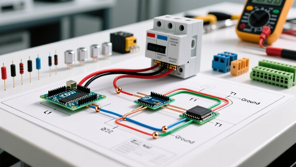

Complete Wiring Diagram for Power Wheels 12V & 24V Upgrades
Upgrading a ride-on toy from a sluggish 12V stock configuration to a high-torque 24V system is one of the most popular DIY electrical projects for parents and hobbyists. However, simply slapping two batteries together without understanding the underlying wiring diagram for Power Wheels is a fast track to melted shifters, tripped breakers, and potential fire hazards. Factory harnesses are engineered for minimal cost and low current draw, meaning they lack the overhead required for performance modifications.
In this vehicle-specific guide, we break down the exact electrical architecture of popular models like the Power Wheels Dune Racer and Jeep Wrangler. We will cover the transition from 12V to 24V, proper relay integration, wire gauge calculations, and modern 2026 battery alternatives like LiFePO4. Whether you are repairing a dead pedal or building a custom drift trike, this reference provides the actionable schematics and safety protocols you need.
Anatomy of the Factory 12V Harness
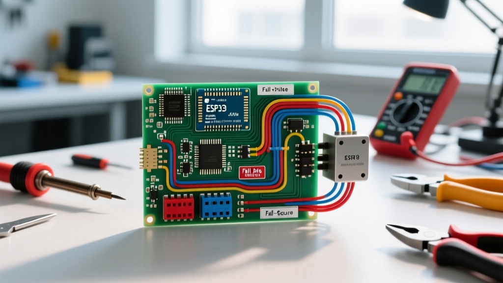
Before modifying the circuit, you must understand the stock topology. A standard 12V Power Wheels harness consists of a 12V 12Ah Sealed Lead Acid (SLA) battery, a thermal circuit breaker (usually 25A or 30A), a foot pedal switch, and a multi-position shifter (Forward/Reverse/High/Low). The motors are typically 550-size or 390-size 12V DC brushed motors.
The most critical weakness in the factory wiring diagram is the shifter. The stock shifter routes the full motor stall current (which can spike to 20A+ per motor on startup) directly through cheap copper contacts and thin 16 AWG or 18 AWG wires. When you double the voltage to 24V, the motors spin faster, draw more current, and generate excessive heat, frequently melting the plastic shifter housing and fusing the contacts.
The 12V to 24V Series Wiring Diagram
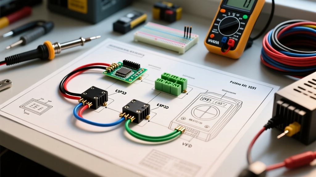
To achieve 24V, you must wire two 12V batteries in series. This doubles the voltage while maintaining the same amp-hour (Ah) capacity. The positive terminal of Battery 1 connects to the negative terminal of Battery 2. The remaining positive (Battery 2) and negative (Battery 1) terminals become your main 24V power supply.
Required Components and 2026 Pricing
| Component | Specification | Estimated Cost |
|---|---|---|
| SLA Batteries | 12V 12Ah (Qty 2) | $60 - $80 |
| Automotive Relay | Bosch-style 5-Pin 40A SPDT | $5 - $8 |
| Thermal Breaker | Bussmann 150-Series 40A Resettable | $10 - $15 |
| Main Power Wire | 12 AWG Silicone Stranded | $15 per spool |
| Smart Charger | 24V 1.5A SLA Smart Charger | $25 - $35 |
Step-by-Step Relay Integration Flow
To protect the stock shifter, we use the shifter only to trigger a high-current automotive relay. The relay handles the heavy lifting, sending 24V directly to the motors.
- Disconnect Power: Remove all batteries and ensure the main breaker is tripped/disconnected.
- Mount the Relay: Secure the 40A Bosch-style relay near the battery compartment using zip ties or double-sided VHB tape.
- Wire the Coil (Signal): Run a 16 AWG wire from the shifter's forward output to Relay Pin 86. Connect Relay Pin 85 to the vehicle's main ground.
- Wire the Contacts (Power): Run 12 AWG wire from the 24V battery positive (through the new 40A breaker) to Relay Pin 30.
- Output to Motors: Run 12 AWG wire from Relay Pin 87 to the motor power input. Pin 87a (Normally Closed) remains unused and should be taped off.
- Test the Circuit: Reconnect batteries, press the pedal, and engage the shifter. You should hear a distinct 'click' from the relay before the motors engage.
Wire Gauge and Thermal Breaker Sizing
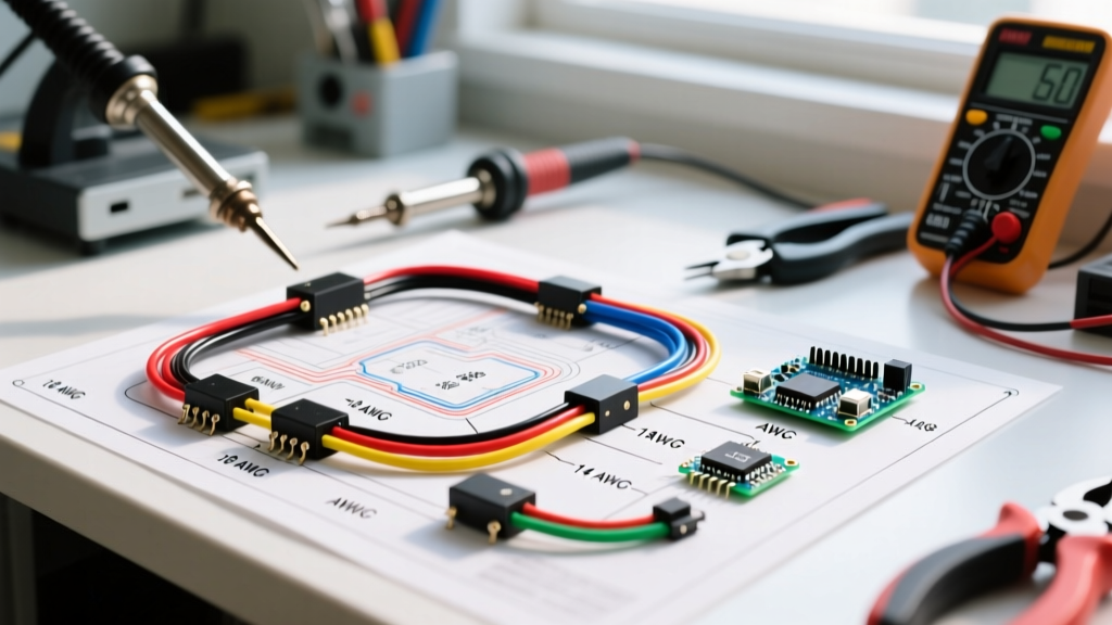
Using the correct wire gauge is non-negotiable. According to the PowerStream Wire Size Chart, 16 AWG wire is only rated for roughly 10 to 13 amps in chassis wiring applications. A 24V Power Wheels setup pushing two 550-size motors can easily sustain 25 amps under load, and spike past 40 amps during a stall or hill climb.
You must upgrade all main power runs (battery to breaker, breaker to relay, relay to motors) to 12 AWG silicone wire. Silicone insulation is preferred over standard PVC because it withstands higher temperatures and remains flexible in cold weather, which is crucial for toys stored in unheated garages. Furthermore, replace the stock 25A thermal breaker with a 40A resettable breaker. If you frequently drive on thick grass or steep inclines, a 50A breaker may be necessary, provided your 12 AWG wiring is kept as short as possible to minimize voltage drop and resistive heating.
SLA vs. LiFePO4: Modern Battery Upgrades
While wiring two SLA batteries in series is the traditional route, the 2026 modding landscape has heavily shifted toward Lithium Iron Phosphate (LiFePO4) batteries. A single 24V LiFePO4 pack offers massive weight savings, zero voltage sag, and a significantly longer lifecycle.
Chemistry Comparison Matrix
| Feature | 2x 12V SLA (Series) | 24V LiFePO4 Pack |
|---|---|---|
| Total Weight | ~18 lbs (8.1 kg) | ~6 lbs (2.7 kg) |
| Voltage Sag Under Load | High (drops to 21V) | Minimal (stays at 25V+) |
| Lifecycle (Cycles) | 200 - 300 | 2000 - 4000 |
| BMS Protection | None | Built-in (Over-discharge/Short) |
| Upfront Cost | ~$70 | ~$110 - $140 |
Expert Warning: Never wire a LiFePO4 battery in series or parallel with an SLA battery. The differing charge profiles and internal resistances will cause the BMS to trip or, worse, lead to thermal runaway. Always use the dedicated LiFePO4 charger provided by the manufacturer.
Bypassing the Stock Shifter (Crucial Edge Case)
If your vehicle uses a complex multi-speed shifter (like the 2-speed Jeep Wrangler models), the internal gearbox and contacts are highly prone to failure under 24V. The most robust wiring diagram for Power Wheels involves entirely bypassing the high-current motor routing inside the shifter.
By opening the shifter housing, you can identify the low-current signal wires. Use a multimeter to find which pin closes the circuit when shifted into 'High'. Run this low-current signal to your relay coil (Pin 86). This transforms the shifter from a high-current mechanical switch into a low-current signal switch, virtually eliminating the chance of melted contacts. For a deeper understanding of how relay switching circuits isolate high and low currents, refer to the Electronics Tutorials Relay Guide.
Troubleshooting Common Failure Modes
Even with a perfect wiring diagram, real-world variables introduce faults. Here is how to diagnose the most common 24V upgrade issues:
- Vehicle moves in reverse but not forward: The forward contact inside the shifter is burnt out. Bypass the shifter using the relay method outlined above, or replace the shifter switch with a heavy-duty 30A toggle switch.
- Breaker trips instantly upon pressing the pedal: You likely have a dead short. Check for pinched 12 AWG wires near the steering column or axle. Alternatively, the motors may be seized; test them by applying 12V directly from a drill battery to ensure they spin freely.
- Relay clicks rapidly (machine-gun effect): This indicates severe voltage sag. The motor draw is dropping the system voltage low enough to de-energize the relay coil, which cuts power, voltage recovers, and the relay engages again. Fix this by upgrading to a LiFePO4 battery or ensuring all ground connections are sanded down to bare metal.
- One motor spins, the other does not: Check the motor gearbox. The plastic planetary gears inside the 550-size motor housings frequently strip under the increased torque of 24V. Replace with steel-ring-gear aftermarket gearboxes.
Safety and CPSC Guidelines
Modifying children's toys inherently alters their safety profile. The CPSC Battery Safety Guidelines emphasize the dangers of short circuits and thermal events in consumer battery products. When building your custom wiring diagram, always use heat-shrink tubing with adhesive lining (marine-grade) on all crimp connections. Electrical tape degrades over time and will unravel in the heat of a summer driveway.
Additionally, install an inline emergency kill switch (a heavy-duty 50A marine battery disconnect) in an easily accessible location under the hood or seat. This allows an adult to instantly cut all power to the vehicle in the event of a stuck pedal or runaway scenario. Finally, never leave a modified 24V vehicle charging unattended, especially if using aftermarket smart chargers that lack UL certification.