
Introduction to 48V DC Traction Systems
Building a custom electric vehicle (EV) or upgrading a fleet golf cart requires a precise understanding of high-current traction circuits. While the broader automotive industry is shifting toward AC induction and PMAC architectures, the wiring diagram for DC motor setups remains a cornerstone of DIY EV conversions, marine winches, and heavy-duty golf cart builds. Series-wound DC motors offer immense starting torque, rugged simplicity, and cost-effectiveness that keep them highly relevant in 2026 for budget-conscious builders and off-road applications.
This guide provides a master-class, vehicle-specific breakdown of wiring a 48V series-wound DC traction motor paired with a high-amperage solid-state controller. We will cover the exact power circuit routing, the critical pre-charge topology, wire gauge selection per NEC standards, and the edge-case failure modes that cause catastrophic component welding.
⚠️ HIGH-CURRENT SAFETY WARNING: A 48V EV system pushing 600A peak generates over 28 kilowatts of power. DC arcs do not self-extinguish like AC arcs. Always install a marine-grade ANL fuse or Class-T fuse on the main battery positive line, and disconnect the main battery bank before torquing terminals. Refer to OSHA Electrical Safety Guidelines for proper lockout/tagout procedures when working on high-current DC banks.
Core Components & 2026 BOM Pricing
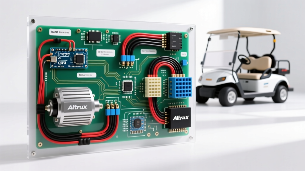
To provide actionable specifics, this wiring guide is based on the most popular DIY EV and golf cart powertrain combo currently on the market: the Advanced DC (ADC) 8-inch Series-Wound Motor paired with an Alltrax DCX controller. Below is the verified Bill of Materials (BOM) with current 2026 market pricing.
| Component | Model / Specification | Estimated 2026 Cost | Function |
|---|---|---|---|
| Traction Motor | ADC 8" Series-Wound (8134-001) | $745.00 | Provides rotational torque via armature and field coils. |
| Motor Controller | Alltrax DCX 48600 (48V, 600A Peak) | $489.00 | PWM modulation of battery voltage to control speed/torque. |
| Main Contactor | Albright SW200-4 (48V Coil, 200A Cont.) | $88.00 | Heavy-duty relay connecting battery bank to controller. |
| Direction Switch | Micro-switch FNR (Forward/Neutral/Reverse) | $35.00 | Logic signaling to controller for field reversal. |
| Main Fuse | Class-T 400A Fuse (Littelfuse) | $42.00 | Short-circuit protection for main battery feed. |
| Cable | 2/0 AWG Ultra-Flex Welding Cable | $4.50 / ft | Main high-current power delivery. |
Step-by-Step Wiring Diagram for DC Motor Power Circuits
The high-current path is the backbone of your EV conversion. Incorrect routing here leads to voltage drop, overheating, and controller failure. The ADC 8-inch motor features four main terminals: A1 and A2 (Armature), and S1 and S2 (Stator/Field).
1. Main Battery to Controller Feed
- Battery Positive (+) routes to the Class-T 400A Fuse.
- From the fuse, run 2/0 AWG cable to the Albright Contactor terminal (Input side).
- The Contactor Output side connects directly to the Alltrax Controller B+ (Battery Positive) terminal.
- Battery Negative (-) routes directly to the Alltrax Controller B- (Battery Negative) terminal. Do not route this through the contactor.
2. Controller to Motor Armature (High Current)
- Run 2/0 AWG cable from the Controller M- (Motor Negative) terminal to the Motor A1 terminal.
- Run 2/0 AWG cable from the Motor A2 terminal back to the Controller B- terminal (or directly to the main battery negative busbar to complete the circuit, depending on controller manual specifics; Alltrax typically uses a dedicated M- for current sensing).
3. Controller to Motor Field (Reversing Logic)
In a series-wound motor, the field coils are wired in series with the armature. To reverse the motor's direction, you must reverse the current flow through EITHER the armature OR the field, but never both. Modern controllers handle this internally via solid-state MOSFET bridges on the field outputs.
- Connect Controller F1 to Motor S1.
- Connect Controller F2 to Motor S2.
Expert Note: Use 4 AWG cable for the F1/F2 field connections. While they carry the full armature current, the physical run is usually very short (under 3 feet) if the controller is mounted near the motor. For runs longer than 4 feet, upgrade to 2/0 AWG to prevent field-weakening voltage drop.
The Pre-Charge Circuit: Preventing Contactor Welding
The most common mistake in DIY wiring diagram for DC motor projects is omitting a pre-charge circuit. The Alltrax DCX controller contains a massive bank of electrolytic capacitors. When the main Albright contactor closes, these empty capacitors act as a dead short, pulling thousands of amps instantaneously. This arc will pit and eventually weld the contactor contacts together, causing a runaway vehicle.
How to wire the pre-charge:
- Install a 150-Ohm, 10-Watt ceramic power resistor in parallel across the input and output terminals of the main Albright contactor.
- When you turn the key to "ON", a smaller relay (or the pre-charge circuit on the ignition switch) sends current through this resistor to slowly charge the controller capacitors.
- After 1-2 seconds, the main contactor coil is energized, closing the high-current path. The resistor is bypassed and safely idle.
Wire Gauge Selection & Terminal Torque Specifications
Sizing your conductors correctly is mandated by the NFPA 70 National Electrical Code (NEC). While EV traction systems fall under specific vehicle exemptions, adhering to NEC Article 310 ampacity tables ensures thermal safety. Furthermore, high-current DC connections vibrate loose; precise torque is non-negotiable.
| Cable Gauge (AWG) | Max Continuous Ampacity | Application | Terminal Torque Spec |
|---|---|---|---|
| 2/0 AWG | 195A (90°C rating) | Main Battery, B+, B-, M-, A1, A2 | 120 in-lbs (13.5 Nm) |
| 4 AWG | 85A (90°C rating) | Field (S1/S2) short runs, FNR power | 80 in-lbs (9.0 Nm) |
| 10 AWG | 35A (90°C rating) | Throttle signal, Contactor coil, Logic | 35 in-lbs (4.0 Nm) |
Advanced Edge Cases & Troubleshooting Matrix
Series-wound DC motors exhibit unique electromagnetic behaviors. If your wiring deviates from the schematic, the results can be destructive. Use this matrix to diagnose abnormal behaviors during your initial bench test.
| Symptom | Root Cause (Failure Mode) | Corrective Action |
|---|---|---|
| Motor "Runaway" (Spins uncontrollably fast with no load) | Open circuit on S1 or S2 field wire. Without field resistance, armature back-EMF cannot build, causing the motor to draw max current and over-rev until mechanical failure. | Immediately kill power. Check continuity on F1/F2 controller terminals and S1/S2 motor studs. |
| Contactor clicks, but motor does not move | Open circuit on A1/A2 armature loop, or blown Class-T main fuse due to a shorted controller MOSFET. | Verify 48V at controller B+ and B- while under load. Check A1/A2 continuity. |
| Motor moves in wrong direction despite FNR switch | FNR logic switch wired to the wrong micro-switch terminals, or both Armature and Field were manually swapped (canceling the reversal). | Ensure only S1/S2 are swapped by the controller logic. Verify FNR switch pinout against Alltrax manual. |
| Severe voltage sag and cable heating at 50% throttle | Undersized cables, or loose crimps causing high-resistance joints. Often occurs when using standard automotive battery cable instead of ultra-flex welding cable. | Replace with 2/0 AWG ultra-flex. Use closed-end copper lugs crimped with a hex-die hydraulic crimper. |
The 2026 Landscape: DC vs. AC Traction Systems
While mastering the wiring diagram for DC motor configurations is essential for legacy fleet repairs, winches, and budget golf cart builds, builders should be aware of the shifting 2026 EV landscape. According to data from the Alternative Fuels Data Center, modern passenger EVs and high-end utility vehicles have almost entirely transitioned to AC Induction and Permanent Magnet AC (PMAC) motors.
Why the shift? Series-wound DC motors cannot easily support regenerative braking. When you lift off the throttle in a DC EV, the vehicle coasts; mechanical friction brakes do all the stopping work. In contrast, AC systems paired with modern inverters can reverse the phase angle to feed kinetic energy back into the battery bank, extending range by 15-20% and drastically reducing brake pad wear. However, AC systems require complex 3-phase wiring, resolver/encoder calibration, and significantly higher component costs (often $2,500+ for the motor and inverter combo). For a $1,500 total budget DIY golf cart or rock-crawler build, the series-wound DC motor remains the undisputed king of torque-per-dollar.
Final Inspection Checklist
Before applying main battery power to your newly wired DC traction system, complete this final physical audit:
- [ ] All 2/0 AWG lugs are hex-crimped and heat-shrunk. No bare copper is exposed near the chassis.
- [ ] Motor terminal nuts are secured with Nord-Lock washers or nylon-insert locknuts to prevent vibration loosening.
- [ ] The controller is mounted flat to an aluminum heat-sink or chassis plate with thermal compound (the Alltrax DCX case is the negative heat sink and requires airflow).
- [ ] Pre-charge resistor is verified with a multimeter (should read ~150 Ohms).
- [ ] Throttle potentiometer (0-5k Ohm or 0-5V Hall effect) is calibrated via the Alltrax PC software before the vehicle is placed on the ground.
By adhering strictly to these wiring topologies and torque specifications, your DC traction system will deliver reliable, high-torque performance for years to come, safely bridging the gap between raw battery power and the pavement.