
Decoding the Standard Motorhome Electrical Wiring Diagram
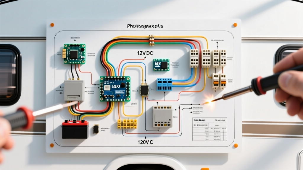
Reading a motorhome electrical wiring diagram requires understanding a unique hybrid of marine and residential electrical standards. Unlike a standard home, an RV operates on a dual-voltage architecture: a 12V DC system for chassis functions and house loads (lights, water pumps, slide-outs), and a 120V AC system for high-draw appliances (air conditioners, microwaves, residential refrigerators). In 2026, with the mass adoption of LiFePO4 lithium battery banks and high-wattage solar arrays, these diagrams have become significantly more complex, integrating sophisticated Battery Management Systems (BMS) and DC-DC chargers.
Before tracing a fault or planning an upgrade, you must understand the visual language of RV schematics. Standard diagrams use specific color codes and symbols that differ slightly from standard NEC residential wiring.
Standard RV Wire Color Code Matrix
| Voltage / System | Wire Color | Function / Application |
|---|---|---|
| 12V DC | Red | Positive (+) from battery to fuse block |
| 12V DC | White or Black | Negative (-) / Ground return to busbar |
| 12V DC | Yellow | Chassis ground or starter signal |
| 120V AC | Black | Hot (Line 1) - 30A/50A Shore Power |
| 120V AC | Red | Hot (Line 2) - 50A Shore Power only |
| 120V AC | White | Neutral (Grounded Conductor) |
| 120V AC | Green or Bare | Equipment Grounding Conductor |
The 12V DC House System: Batteries, BMS, and Fuse Blocks
The heart of the 12V DC diagram is the battery bank and the primary DC distribution panel. In modern motorhomes, you will typically see a Victron SmartShunt or similar BMS monitor installed directly on the negative terminal. This is a critical diagram reference point: all negative loads must pass through the shunt before reaching the negative busbar, otherwise, your battery monitor will read inaccurately.
Wire Sizing and Voltage Drop Realities
A common failure mode in RV wiring is undersized DC cabling. Because 12V systems require high amperage to deliver adequate wattage (Watts = Volts × Amps), voltage drop over distance is severe. For example, a 2000W inverter pulling from a 12V bank will draw roughly 175 Amps continuously. According to Victron Energy's Wiring Unlimited Guide, a 175A draw requires 2/0 AWG pure copper wire for runs up to 10 feet to maintain a voltage drop below 3%. Using standard automotive wire or undersized 4 AWG cable will result in melted lugs, inverter low-voltage cut-offs, and potential fire hazards.
- Fuse Block Reference: Look for the Blue Sea Systems ST Blade fused block on the diagram. It should be fed by a main Class T fuse (e.g., 250A for a 200Ah lithium bank) located within 7 inches of the battery positive terminal.
- Slide-Out Motors: Diagrams will show slide-out motors wired directly to heavy-duty solenoids (like the Trombetta 12V 200A solenoid), bypassing standard blade fuses in favor of 6 AWG wiring and 80A ANL fuses.
120V AC Shore Power & Inverter Integration
Tracing the 120V AC side of a motorhome electrical wiring diagram starts at the shore power inlet—typically a 30A (TT-30R) or 50A (14-50R) receptacle. The power flows into an Automatic Transfer Switch (ATS) or directly into an Inverter/Charger with a built-in transfer switch, such as the Victron MultiPlus-II 12/3000/120.
Critical Safety Warning: Neutral-Ground Bonding
In standard residential wiring (NEC Article 250), the neutral and ground are bonded only at the main service panel. In an RV, the inverter/charger must internally manage this bond. When running on shore power, the neutral-ground bond must be broken inside the RV to prevent backfeeding current onto the shore power ground wire. When running on inverter power, the bond must be closed to allow GFCI outlets to trip during a fault. Modern diagrams will show an internal relay in the inverter handling this; never manually bond neutral and ground on an RV subpanel.
The 50A vs. 30A Split-Phase Diagram Difference
If your diagram shows a 50A inlet, you are dealing with a 120/240V split-phase system (two 120V hot legs, L1 and L2, sharing a neutral). A frequent edge-case failure occurs when a 50A RV is plugged into a 30A pedestal using a 'dogbone' adapter. If the pedestal's 30A receptacle is miswired with 240V instead of 120V, both L1 and L2 on the RV will receive 240V, instantly destroying the RV's power converter and microwave. Always verify pedestal voltage with a multimeter before connecting.
Solar & DC-DC Alternator Charging Topologies
Modern motorhome diagrams heavily feature solar and alternator charging circuits. When reading these schematics, locate the MPPT (Maximum Power Point Tracking) charge controller and the DC-DC charger.
- Solar Input (MPPT): Solar panels are wired in series or parallel to an MPPT controller (e.g., Victron SmartSolar MPPT 100/30). The diagram will show a DC disconnect breaker and a surge protector between the roof panels and the controller to prevent inductive voltage spikes from frying the controller during a disconnect.
- Alternator Charging (DC-DC): To charge a lithium house bank from the chassis alternator, diagrams utilize a DC-DC charger (like the Renogy 40A DC-DC or Victron Orion-Tr Smart). This device isolates the house bank from the chassis start battery and steps down the alternator's high-voltage output (often 14.4V+) to a safe charging profile for LiFePO4, preventing alternator burnout.
Troubleshooting Matrix: Tracing Common RV Electrical Faults
Use this matrix in conjunction with your specific motorhome electrical wiring diagram to isolate common power failures.
| Symptom | Probable Root Cause | Diagram Trace Point & Action |
|---|---|---|
| 12V lights flicker when water pump turns on | Severe voltage drop on 12V main bus; loose neutral on DC busbar. | Trace main battery cables to the negative busbar. Check for corrosion or loose set-screws on the 2/0 AWG lugs. |
| Shore power connects, but AC outlets are dead | Failed Automatic Transfer Switch (ATS) or tripped GFCI master outlet. | Locate the ATS on the diagram. Bypass the ATS temporarily to test. Check the master GFCI in the bathroom or kitchen. |
| Inverter shuts down immediately under load | Undersized DC wiring causing voltage sag below 10.5V cutoff. | Measure voltage directly at the inverter DC terminals under load, not at the battery. If it drops >1V, upgrade wire gauge. |
| Chassis battery drains while parked (boondocking) | Failed Battery Isolator Relay (BIRD) or parasitic DC draw. | Locate the BIRD solenoid on the diagram. Test for continuity between chassis and house banks when the inverter is off. |
Code Compliance & Authoritative Standards
When modifying or designing a motorhome electrical wiring diagram, adherence to safety codes is non-negotiable. In the United States, RV electrical systems are governed by NFPA 1192 (Standard for Recreational Vehicles)NEC Article 551. These codes dictate everything from the required ampacity of shore power cords to the specific placement of GFCI receptacles near water sources. For detailed safety standards and consumer guidelines, refer to the RV Industry Association (RVIA) Consumer Safety Resources. Furthermore, understanding the NFPA 1192 Standard for Recreational Vehicles is critical for anyone performing custom 120V AC wiring or lithium battery retrofits in Class A, B, or C motorhomes.
Frequently Asked Questions (FAQ)
Where can I find the wiring diagram for my specific motorhome?
Manufacturers rarely publish full schematics online. You can usually find a basic 12V/120V diagram in the owner's manual packet, tucked inside the electrical cabinet, or by contacting the manufacturer's support with your specific chassis and coach VIN numbers. For custom builds, the upfitter or conversion company (e.g., Winnebago, Thor, Airstream) holds the master CAD schematics.
Can I use automotive wire instead of marine-grade wire for RV DC circuits?
While automotive wire (SAE J1128) is common in chassis wiring, it is highly recommended to use marine-grade, tinned copper wire (UL 1426) for the 12V house system. The tinned coating prevents black oxidation (copper creep) inside crimps and lugs, which is a leading cause of high-resistance joints and fires in the high-vibration environment of a motorhome.
Why does my motorhome diagram show two separate ground busbars?
Best practice diagrams separate the 12V DC negative return busbar from the 120V AC equipment grounding busbar. They are only bonded together at a single point (usually the chassis frame or the inverter's internal bonding relay) to prevent AC stray currents from traveling through DC ground wires, which can cause severe galvanic corrosion and electronic interference.