
Decoding the Wiring Diagram for Trane Air Conditioner Systems
Interpreting a wiring diagram for Trane air conditioner units requires a clear understanding of both high-voltage power distribution and low-voltage control logic. Whether you are commissioning a standard single-stage Trane XR15 or a variable-speed Trane XV20i inverter system, the fundamental architecture remains consistent: a 240V power circuit feeds the outdoor condenser, while a 24VAC control circuit dictates compressor staging, fan speeds, and reversing valve states. As of the 2026 NEC cycle, strict adherence to NFPA 70 (National Electrical Code) Article 440 is mandatory for all HVAC installations, particularly regarding disconnect visibility and branch circuit sizing.
This step-by-step walkthrough dissects the exact wiring pathways, terminal designations, and failure modes associated with modern Trane split systems. We will bypass generic theory and focus on actionable, field-tested wiring procedures.
High-Voltage vs. Low-Voltage Architecture
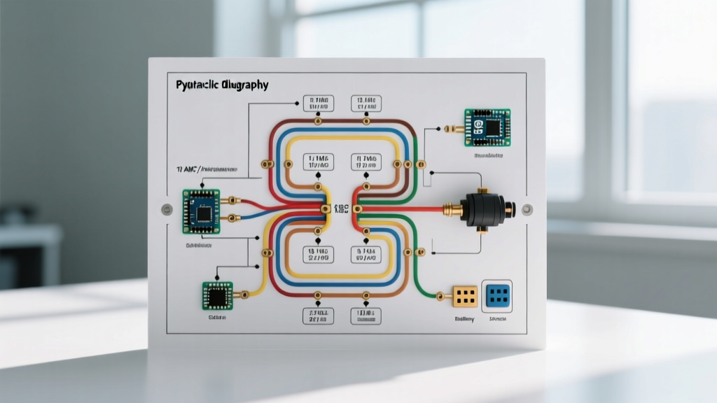
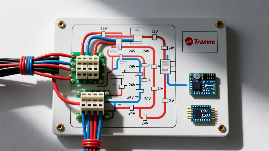
Trane schematics divide the electrical system into two isolated zones. The high-voltage (HV) side handles the compressor contactor, condenser fan motor, and crankcase heater. The low-voltage (LV) side manages the thermostat signals, defrost board logic, and safety interlocks (high/low-pressure switches). Crossing these circuits will instantly destroy the integrated furnace control (IFC) board or the outdoor defrost board.
| Terminal | Voltage | Function | Wire Color (Typical) |
|---|---|---|---|
| L1 / L2 | 240VAC | Main Power Input from Disconnect | Black / Red (or White re-identified) |
| C (Contactor) | 24VAC | Compressor Contactor Coil Common | Blue or Yellow |
| Y (Contactor) | 24VAC | Compressor Contactor Coil Signal | Yellow |
| O / B | 24VAC | Reversing Valve (Heat Pump Only) | Orange |
| DF / DT | 24VAC | Defrost Thermostat / Sensor Inputs | Pink / Brown |
Step-by-Step Wiring Walkthrough
Step 1: Sizing and Routing the High-Voltage Whip
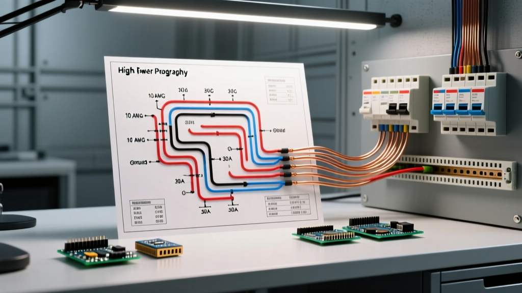
The branch circuit supplying the outdoor unit must be sized according to the Minimum Circuit Ampacity (MCA) listed on the Trane data plate, not the compressor's RLA (Rated Load Amps). For a typical 3-ton Trane XR15, the MCA is usually around 20A to 24A, requiring a 30A double-pole breaker and 10 AWG copper wire. In early 2026, 10/2 NM-B cable costs approximately $1.65 per foot, while 10 AWG THHN in conduit runs about $0.45 per foot.
- Overcurrent Protection: Use the Maximum Overcurrent Protection (MOP) value on the data plate to size the breaker. If MOP is 40A, use 8 AWG wire and a 40A breaker, even if MCA is lower.
- Conduit & Whip: Use a minimum 1/2-inch liquid-tight flexible metal conduit (LFMC) for the final 6 feet from the disconnect to the unit. Secure the LFMC within 12 inches of the disconnect and the condenser panel.
- Grounding: A dedicated equipment grounding conductor (EGC) must be pulled with the circuit conductors. Do not rely on the conduit as the sole ground path.
Step 2: Terminating the Outdoor Disconnect
The 2026 NEC requires the disconnecting means to be within sight of the air conditioning equipment and readily accessible. Install a 60A, 240V NEMA 3R-rated pull-out or fusible disconnect box ($35-$55 at most electrical suppliers).
- Strip 3/4 inch of insulation from the 10 AWG or 8 AWG conductors.
- Terminate the Line (L1/L2) wires from the main panel to the top lugs of the disconnect.
- Terminate the Load wires (feeding the condenser) to the bottom lugs.
- Terminate the bare copper EGC to the equipment ground bus bar. Torque all lugs to the manufacturer's specification (typically 20-25 in-lbs for small lug blocks) to prevent thermal arcing.
Step 3: Low-Voltage Control Wiring (24VAC)
The control circuit originates at the indoor air handler's IFC board or a dedicated 24VAC transformer. You will route an 18/8 stranded thermostat cable to the outdoor unit. According to the U.S. Department of Energy's HVAC installation guidelines, proper control wiring prevents signal degradation and ghost voltage issues that cause contactor chatter.
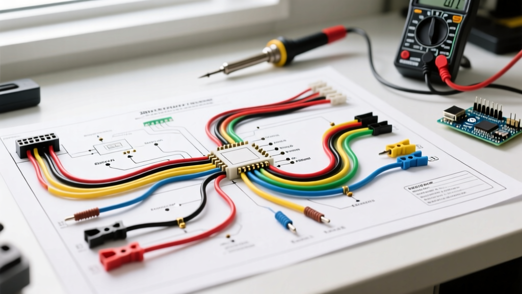
- Y (Yellow): Connect to the 'Y' terminal on the defrost board or contactor coil. This energizes the compressor.
- C (Blue/Brown): Connect to the 'C' (Common) terminal. This completes the 24VAC circuit. Critical: Never use the ground wire as a common. Doing so will cause stray voltage and trip GFCI/AFCI breakers indoors.
- O (Orange): For Trane heat pumps, the O terminal energizes the reversing valve in cooling mode. Ensure this is not swapped with the B terminal, or the unit will default to heating mode and trigger a high-pressure fault.
Step 4: Trane ComfortLink II vs. Standard Thermostat Integration
Modern Trane systems often utilize communicating technology rather than traditional 24V on/off signals. If you are wiring a Trane XV20i or XL16i with a ComfortLink II thermostat, the wiring diagram changes drastically.
| Feature | Standard 24V (e.g., XR15) | ComfortLink II (e.g., XV20i) |
|---|---|---|
| Cable Type | 18/8 Stranded Unshielded | 18/4 Shielded Twisted Pair (STP) |
| Terminals Used | R, C, Y, Y2, W, G, O/B | A, B, C, D (Data Bus) |
| Voltage on Bus | 24VAC (Analog signals) | 24VDC / 15VDC (Digital Data) |
| Polarity | Not Sensitive | Strictly Sensitive (A to A, B to B) |
Expert Warning: Never apply standard 24VAC from a legacy thermostat wire to the A/B/C/D data bus terminals on a Trane communicating outdoor unit. This will instantly fry the EEPROM chip on the main inverter board, resulting in a $600 to $900 replacement cost.
Common Wiring Failure Modes & Diagnostics
Even with a correct wiring diagram for Trane air conditioner setups, field conditions introduce variables that lead to specific failure modes. Here is how to diagnose the most common electrical faults:
1. The Blown 3A Fuse on the Control Board
Trane indoor air handlers and outdoor defrost boards utilize a standard 3-amp automotive-style (ATO) blade fuse on the 24VAC hot leg. If this fuse blows immediately upon a call for cooling, you have a direct short to ground. Diagnostic Step: Disconnect the Y and C wires at the outdoor unit. Replace the 3A fuse and call for cooling. If the fuse holds, the short is in the outdoor contactor coil or the wire splice. If it blows again, the short is in the thermostat wire between the indoor and outdoor units.
2. Contactor Chatter and Coil Burnout
If the outdoor contactor rapidly clicks or hums loudly without fully pulling in, the coil is receiving insufficient voltage. This is almost always caused by voltage drop on long thermostat wire runs. If the run exceeds 75 feet, the resistance of 18 AWG wire drops the voltage below the 18VAC pull-in threshold of the Trane contactor coil. Solution: Upgrade the Y and C conductors to 16 AWG, or install a 24VAC relay booster at the outdoor unit.
3. Reversing Valve Solenoid Overheating
On Trane heat pumps, the reversing valve solenoid draws roughly 0.6 amps. If the O/B wire is undersized, or if a standard 24V thermostat is incorrectly configured to energize the B terminal (heating) instead of the O terminal (cooling), the solenoid may remain partially energized or overheat. Always verify the Trane defrost board jumper settings; most modern Trane boards require the 'O' jumper to be cut or moved for standard cooling-first operation.
Code Compliance and Safety Standards
Working on HVAC electrical systems carries severe arc flash and electrocution risks. The Occupational Safety and Health Administration (OSHA) mandates strict lockout/tagout (LOTO) procedures before opening any condenser panel. Always verify the absence of voltage using a CAT III or CAT IV multimeter at the L1 and L2 terminals on the contactor before touching any internal wiring.
Furthermore, ensure all low-voltage wires are routed through separate knockouts from the high-voltage wires to prevent electromagnetic interference (EMI) and insulation breakdown. Secure all wires with UV-rated zip ties, keeping them clear of the condenser fan blade path and sharp sheet metal edges. By strictly following this wiring diagram for Trane air conditioner systems and adhering to current NEC standards, you ensure optimal system longevity, peak SEER2 efficiency, and absolute operational safety.