
Bridging Lighting and Motor Mechanics: The Dual-Purpose Fixture
When most DIYers search for a standard wiring diagram for ceiling light fixtures, they expect a simple three-wire connection: hot, neutral, and ground. However, when that ceiling light is integrated into a ceiling fan assembly, you are no longer just wiring a lamp; you are wiring a Permanent Split Capacitor (PSC) motor alongside a lighting circuit. As of the 2026 National Electrical Code (NEC) updates, treating a motorized light fixture as a standard lighting load is a common code violation that leads to overheated junction boxes and premature motor failure.
This motor wiring tutorial breaks down the exact electrical architecture of ceiling fan and light kit combinations. We will cover the internal PSC motor windings, the critical run capacitor, the light kit socket integration, and how to properly wire modern smart-canopy receivers.
Why Motor Wiring Differs from Standard Lighting
A standard LED ceiling light draws a purely resistitive or slightly capacitive load, typically peaking at 0.2 to 0.5 amps. A ceiling fan motor, conversely, is an inductive load. When a PSC motor starts, it experiences Locked Rotor Amperage (LRA), which can briefly spike to 3 or 4 times its running amperage. If your wiring diagram for ceiling light and fan combos does not account for this inductive spike and the continuous thermal load of the motor windings, you risk voltage drop, flickering lights, and tripped breakers.
Code Alert: Under NFPA 70 (NEC) Article 314.27, ceiling boxes supporting motorized fans must be specifically listed for fan support and rated for a minimum of 35 pounds, with heavy-duty boxes rated for up to 70 pounds. Standard light-only pancake boxes will fail under motor vibration.
Essential Tools and Material Specifications
Before opening the canopy, ensure your materials match the electrical demands of a combined motor and lighting circuit. The following specifications apply to standard residential 120V, 60Hz systems powering fixtures like the Hunter Builder Elite (Model 53091) or Hampton Bay Rockport (Model 52372).
| Component | Specification / Rating | Purpose & Code Requirement |
|---|---|---|
| Supply Wire Gauge | 14 AWG (15A Circuit) or 12 AWG (20A Circuit) | Handles motor LRA spikes without excessive voltage drop. |
| Junction Box | UL-Listed Fan-Rated (e.g., Saf-T-Brace) | Required by NEC 314.27(D) to withstand motor torque. |
| Run Capacitor | Dual 4.5µF / 6.0µF (250V AC) | Creates phase shift for PSC motor start winding. Costs $12-$18. |
| Light Kit Socket | Medium Base (E26), Max 60W per socket | Must be wired with neutral to the threaded shell (NEC 410.50). |
| Wire Nuts | Ideal Wing-Nut #2 or #3 (Tan/Red) | Ensures solid connection for inductive motor loads. |
Step-by-Step Wiring Diagram for Ceiling Light and Fan Motor
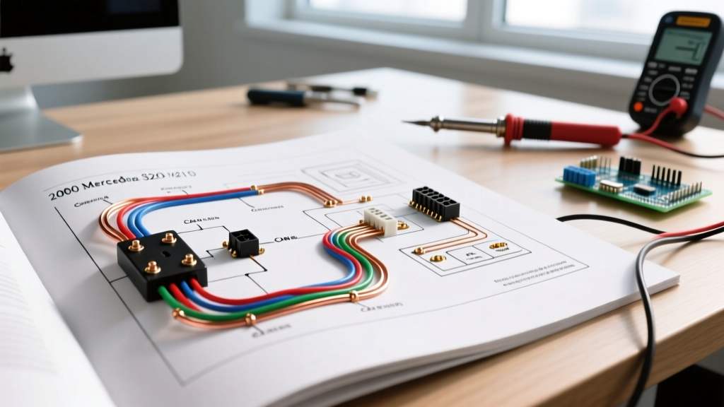
Understanding the wiring diagram for ceiling light and motor combinations requires dividing the process into three distinct phases: the supply connection, the motor winding integration, and the light kit branching.
Phase 1: Prepping the Junction Box and Supply Wires
Turn off the power at the breaker and verify with a non-contact voltage tester (e.g., Klein NCVT-3). In a standard switch-loop or direct-feed scenario, you will have three wires coming from the ceiling: Black (Hot), White (Neutral), and Bare/Green (Ground).
- Grounding the Motor Housing: The motor housing is conductive metal. Connect the supply ground wire directly to the green ground screw on the fan's mounting bracket, and pigtail it to the green/bare wire from the fan's downrod assembly. This prevents the motor housing from becoming energized in the event of an internal winding short.
- Securing the Canopy: Feed the fan's 4-wire harness (Black, Blue, White, Green) through the canopy cover before making any electrical connections.
Phase 2: Connecting the Motor Windings and Capacitor
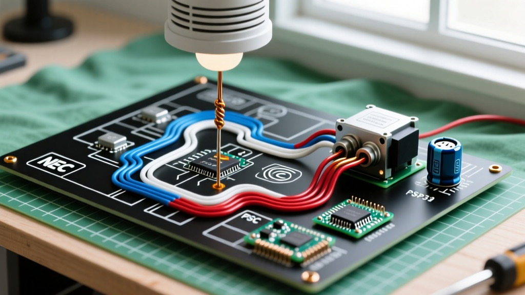
Inside the fan's switch housing sits the PSC motor's run capacitor. The wiring diagram for the motor itself usually features a black wire (main run winding) and a blue or red wire (start winding routed through the capacitor). In pre-assembled residential fans, this internal wiring is sealed, and you only interact with the external harness.
Connect the Black wire from the fan harness to the Black (Hot) supply wire. This provides continuous power to the motor's main run winding and the internal speed controller. Connect the White wire from the fan harness to the White (Neutral) supply wire. This completes the circuit for both the motor and the integrated light kit.
Phase 3: Integrating the Light Kit Socket
The Blue wire on the fan harness is dedicated exclusively to the ceiling light kit. If your wall switch controls both the fan and the light simultaneously, connect the Blue wire to the same Black (Hot) supply wire using a wire nut. If you have a dual-switch setup (one for fan, one for light), connect the Blue wire to the secondary hot wire (often Red) coming from the ceiling.
Critical Safety Note: According to ENERGY STAR and NEC guidelines, the neutral wire must always be connected to the threaded metal shell of the light bulb socket, while the hot wire connects to the center brass contact. Reversing this leaves the socket shell energized, creating a severe shock hazard when changing bulbs.
Modern Smart Receiver Integration (2026 Standard)
In 2026, most new ceiling light and fan combos include an RF or Wi-Fi smart receiver module (such as the Bond Bridge compatible modules or Hunter SIMPLEconnect). This module alters the traditional wiring diagram for ceiling light setups.
The receiver sits inside the canopy and acts as a middleman. The supply Hot and Neutral wires connect to the receiver's AC IN terminals. The receiver's output wires then connect to the fan harness. The receiver uses internal triacs to pulse-width modulate (PWM) the power to the motor for speed control, and steps down the voltage for the light kit dimming. If bypassing a smart receiver to return to manual wall-switch control, you must remove the module entirely and wire the fan harness directly to the ceiling supply wires as outlined in Phase 2 and 3.
Common Failure Modes and Motor Troubleshooting
When a ceiling fan and light combo fails, DIYers often blame the wiring diagram for ceiling light connections, when the actual fault lies within the motor's internal components.
1. Motor Hums but Blades Do Not Spin
The Culprit: A failed run capacitor. The PSC motor relies on the capacitor to create a phase shift in the start winding. If the capacitor degrades (common after 5-7 years of heat exposure in the canopy), the motor lacks the starting torque.
The Fix: Open the switch cup below the motor. Locate the black rectangular capacitor (e.g., 4.5µF). Use a multimeter with a capacitance setting (like the Fluke 117) to test it. If the reading is below 3.8µF, replace it. A replacement costs roughly $15 at electrical supply stores.
2. Light Flickers When Fan is on High Speed
The Culprit: Voltage drop caused by undersized wiring or a loose neutral connection. When the motor draws maximum amperage on high speed, a poor neutral connection will cause the voltage at the light kit to fluctuate.
The Fix: Check the wire nuts connecting the White wires in the canopy. Ensure no bare copper is exposed and that the wires are twisted tightly before the nut is applied. Upgrade to wing-nut connectors for a more secure grip on the inductive load.
3. Fan Runs Backwards on Forward Setting
The Culprit: Incorrect wiring of the forward/reverse toggle switch inside the motor housing. While rare in factory-sealed units, this happens if the internal harness was repaired or replaced.
The Fix: The reverse switch simply swaps the polarity of the start winding relative to the run winding. Consult the manufacturer's specific schematic to ensure the blue and black internal leads are correctly seated on the DPDT (Double Pole Double Throw) switch terminals.
Frequently Asked Questions
Can I use a standard dimmer switch for the ceiling light and fan motor?
No. Standard leading-edge or trailing-edge dimmers are designed strictly for resistive lighting loads. If you wire a fan motor to a standard dimmer, the chopped AC waveform will cause the motor windings to overheat, emit a loud humming noise, and eventually melt the internal insulation, creating a fire hazard. You must use a switch specifically rated for combined fan/light control, or separate the circuits.
What happens if I wire the hot and neutral in reverse on the ceiling light kit?
The light will still turn on, but the threaded metal shell of the bulb socket will become energized with 120V. If you touch the shell while changing a bulb, and your body provides a path to ground, you will receive a severe shock. Always verify that the white neutral wire maps to the socket shell.