
The Evolution of Automotive Electrical Architecture
If you are still referencing a generic 1990s wiring diagram for car stereo installations, you are operating on outdated data. As of 2026, modern vehicle electrical systems are highly complex multiplexed networks. The traditional 12-volt analog switched wire has been largely replaced by CAN (Controller Area Network), CAN-FD, and LIN (Local Interconnect Network) buses. Attempting to tap into factory wiring without a vehicle-specific schematic and a dedicated data interface is a fast track to triggering dashboard error codes, draining the battery, or frying a Body Control Module (BCM).
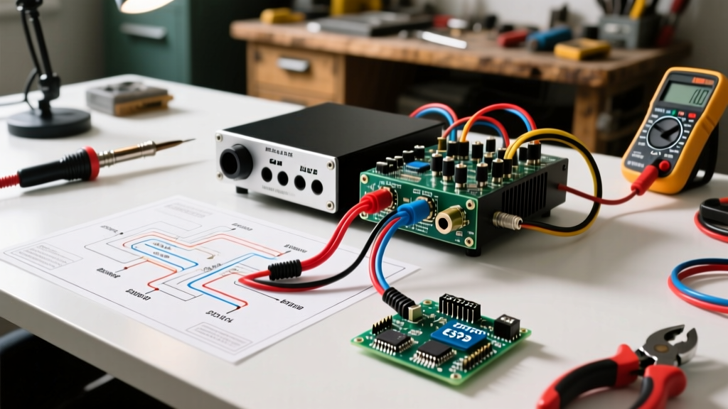
This guide provides a comprehensive, step-by-step walkthrough for reading and executing a wiring diagram for car audio integration—specifically focusing on installing a high-output DSP (Digital Signal Processor) amplifier using a factory T-harness data interface. We will use the installation of a JL Audio VX800/8 DSP/Amplifier paired with a PAC RP7-CH11 RadioPro interface in a late-model Stellantis (Jeep/Ram) vehicle as our practical baseline.
Deconstructing the Wiring Diagram for Car Audio Systems
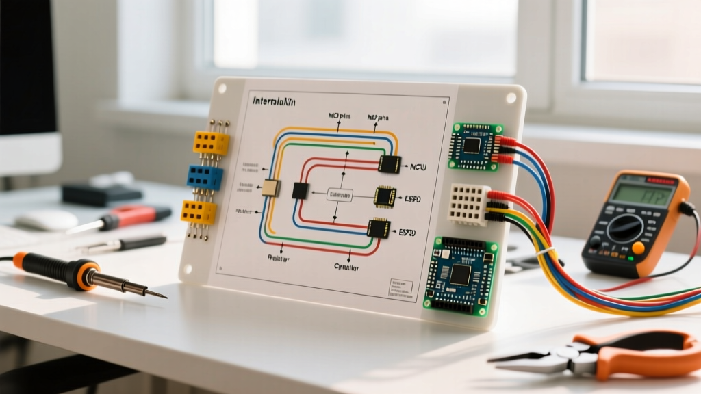
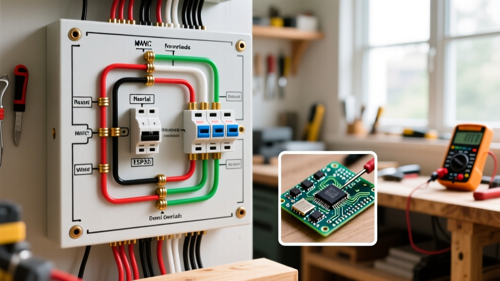
A professional installation requires cross-referencing three distinct diagrams: the power distribution schematic, the factory data-bus pinout, and the DSP signal flow matrix. Relying on a single, flattened diagram often leads to critical oversights, such as ignoring the remote turn-on logic or misinterpreting high-level signal summing requirements.
Expert Warning: The CCA Wire Trap
Never use Copper-Clad Aluminum (CCA) wire for high-current automotive applications. While cheaper upfront, CCA oxidizes rapidly under automotive hood temperatures and vibration. By year two, the aluminum core degrades, increasing resistance and causing severe voltage drop. Always specify 100% Oxygen-Free Copper (OFC) wire, such as KnuKonceptz Kolossus or Stinger XP series, which maintains stable conductivity and meets SAE J1128 standards.
Step-by-Step Walkthrough: Power, Data, and Signal Routing
Step 1: Power and Ground Execution (The 0.5V Rule)
The foundation of any car audio wiring diagram is the power delivery network. The JL Audio VX800/8 features eight channels of amplification and requires substantial current. Undersized power wire is the leading cause of amplifier thermal shutdown and clipping.
- Main Power Run: Route 4 AWG OFC power wire from the positive battery terminal to the amplifier location. Install a 120A ANL fuse (such as the Stinger SPF52120) within 18 inches of the battery positive post.
- Terminal Torque: When connecting to a secondary battery post (like the Stinger SPP68), torque the M6 set screws to exactly 5-7 Nm. Over-torquing strips the soft brass threads; under-torquing creates micro-arcing and heat.
- The Grounding Protocol: Do not rely on seatbelt bolts for high-current grounds. Locate a factory chassis weld nut, sand away the paint and primer to bare metal using 80-grit sandpaper, and secure the 4 AWG ground ring terminal with an M8 bolt. Apply dielectric grease over the connection to prevent galvanic corrosion.
- Voltage Drop Testing: With the engine running and the DSP processing a 50Hz bass tone at 110dB, use a digital multimeter to measure voltage at the battery, then at the amplifier's B+ and GND terminals. The difference must not exceed 0.5V. If it does, your wire gauge is insufficient or your ground is compromised.
Step 2: Decoding the Data Bus and Remote Turn-On
Modern vehicles do not provide a 12V accessory wire at the head unit. Instead, the radio wakes up via a CAN bus message. To extract a remote turn-on signal and retain factory chimes, we use the PAC RP7-CH11 interface.
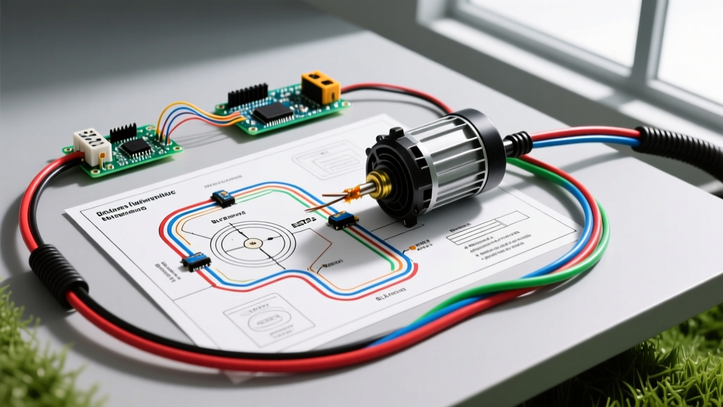
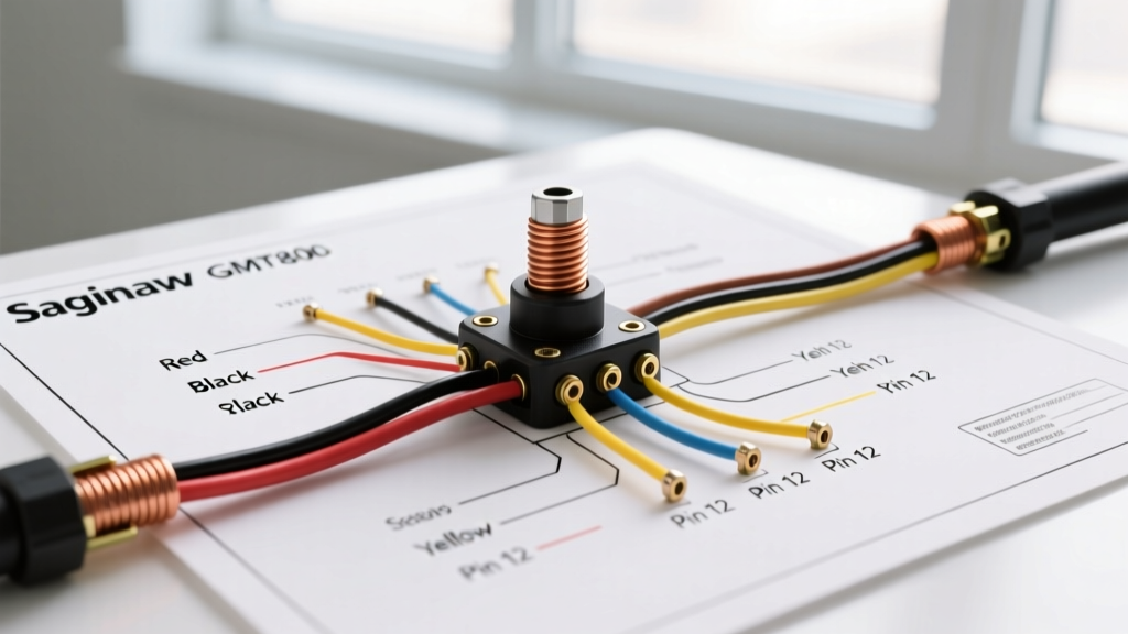
- CAN High and CAN Low: The wiring diagram for this interface will highlight a twisted pair of wires (usually White/Red and White/Black). These connect to the vehicle's CAN-C network. Never untwist more than 1 inch of this pair, as doing so compromises the impedance and invites electromagnetic interference (EMI) from the alternator.
- Chime Retention: The RP7-CH11 intercepts the factory radio's audio chime data and routes it through a small internal amplifier, outputting it to the front left speaker wire. Your DSP wiring diagram must account for this by summing the front left high-level input correctly to avoid phase cancellation of safety alerts.
- Remote Out: The interface provides a dedicated 12V, 2A remote turn-on output (Blue wire). Connect this directly to the 'Remote In' terminal on the JL Audio VX800/8.
Step 3: High-Level Signal Integration and DSP Configuration
Factory amplified systems apply aggressive equalization, time alignment, and all-pass filters to cheap paper speakers. If you feed this processed signal directly into your aftermarket DSP, you will inherit all the factory audio flaws.
The wiring diagram for car audio DSP integration requires utilizing the Automatic Signal Summing and De-EQ features. Connect the factory speaker outputs from the PAC interface to the high-level inputs on the JL Audio DSP. Using the JL Audio TwK software, run the automatic signal summing tool. The DSP will analyze the factory output, invert phase where necessary, and flatten the factory EQ curve, providing a clean, flat pre-amp signal for your aftermarket speakers.
Wire Gauge and Amperage Matrix for 12V Systems
Selecting the correct wire gauge is dictated by the maximum current draw and the total length of the run (positive + negative). The table below is based on a 3% maximum voltage drop at 14.4V, aligning with Mobile Electronics Certification Program (MECP) guidelines.
| Max Current Draw | 0 - 10 ft Run | 10 - 20 ft Run | 20 - 30 ft Run | Recommended Fuse |
|---|---|---|---|---|
| 20A - 35A | 12 AWG OFC | 10 AWG OFC | 8 AWG OFC | 40A ATO |
| 35A - 60A | 8 AWG OFC | 6 AWG OFC | 4 AWG OFC | 60A ANL |
| 60A - 100A | 4 AWG OFC | 4 AWG OFC | 2 AWG OFC | 100A ANL |
| 100A - 150A | 2 AWG OFC | 1/0 AWG OFC | 1/0 AWG OFC | 150A ANL |
| 150A - 200A+ | 1/0 AWG OFC | 2/0 AWG OFC | 2/0 AWG OFC | 200A Class T |
Troubleshooting Common Wiring Diagram Misinterpretations
Failure Mode 1: Alternator Whine and Ground Loops
If you hear a high-pitched whine that scales with engine RPM, you have created a ground loop. This happens when the amplifier, DSP, and source unit are grounded at different chassis points with varying electrical potentials. The Fix: Star-ground all audio components. Run individual ground wires from the DSP, amplifier, and any line drivers to a single, centralized distribution block, and run one massive ground cable from that block to the chassis.
Failure Mode 2: Parasitic Draw and CAN Bus Sleep Failure
A common issue when tapping into modern vehicle networks is preventing the BCM from entering 'sleep' mode. If your wiring diagram for car accessories shows a constant 12V feed powering a module that monitors the CAN bus, the module will keep the network awake, draining the battery overnight. The Fix: Always use interfaces that feature a data-sense sleep mode, or wire the accessory's main power through a heavy-duty relay (like a Bosch JD1914) triggered by a true ignition source, ensuring the CAN transceiver powers down completely when the vehicle is locked.
Failure Mode 3: Clipping on High-Level Inputs
Many factory amplified systems output up to 10V RMS on speaker wires. Feeding this into a DSP with a maximum input sensitivity of 4V will cause immediate input clipping and harsh distortion. The Fix: Consult your DSP manual. The JL Audio VX series features a specific 'High-Level Input' switch that engages an internal voltage divider, safely stepping down 10V signals to line-level without degrading the signal-to-noise ratio.
Final Verification and System Commissioning
Before reassembling the vehicle's interior trim, perform a comprehensive continuity and short-circuit test. Disconnect the amplifier and DSP from the power source. Use a multimeter in continuity mode to verify there is zero continuity between the main power wire and the vehicle chassis. Once verified, reconnect the main fuse, turn on the ignition, and verify the remote turn-on sequence. For further reading on standardized installation practices and advanced troubleshooting, refer to the Crutchfield Learning Center and SAE International automotive electrical standards.
Mastering the wiring diagram for car audio and data integration separates amateur hobbyists from professional installers. By respecting the vehicle's network architecture, using OFC materials, and adhering to strict voltage-drop tolerances, you ensure a system that sounds incredible and operates reliably for the life of the vehicle.