
Understanding the Modern Honeywell (Resideo) Ecosystem
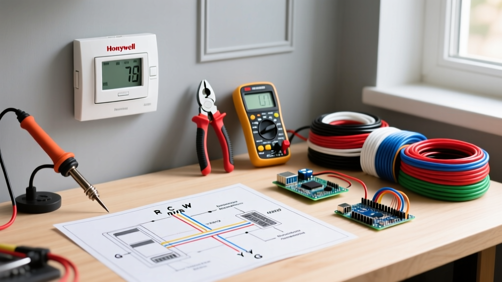
Deciphering the correct wiring diagram for Honeywell thermostat models is a critical skill for both DIY homeowners and HVAC professionals. As of 2026, the Honeywell Home brand—officially operating under the Resideo umbrella—dominates the smart climate control market with advanced models like the T9 (RTH9585WF), the T10 Pro Smart, and the legendary VisionPRO 8000 (TH8320R1003). While these modern units feature Wi-Fi connectivity, geofencing, and Matter protocol support for smart home integration, they all rely on the foundational 24VAC low-voltage wiring standards established decades ago.
Misinterpreting a thermostat wiring diagram can lead to catastrophic results, including blowing the 3-amp or 5-amp automotive-style fuse on your furnace's Integrated Furnace Control (IFC) board, or worse, frying the 24-volt transformer. This comprehensive reference guide breaks down terminal designations, system configurations, and advanced Installer Setup (ISU) codes to ensure a flawless installation.
Comprehensive Terminal Reference Chart
Before touching any wires, you must understand the standard terminal nomenclature. While wire colors are not strictly mandated by the National Electrical Code (NEC) for low-voltage control circuits, industry standards have established typical color-coding. Below is the definitive terminal reference for Honeywell T-Series and VisionPRO models.
| Terminal | Function | Standard Wire Color | System Application |
|---|---|---|---|
| R / Rc / Rh | 24VAC Power (Hot) | Red | All Systems (Rc for Cooling, Rh for Heating) |
| C | 24VAC Common | Blue or Black | Required for Wi-Fi/Smart Models |
| W / W1 | Primary Heat Stage 1 | White | Conventional & Heat Pump |
| W2 / Aux / E | Auxiliary / Emergency Heat | White or Black | Heat Pump with Electric/Gas Backup |
| Y / Y1 | Primary Cool / Compressor Stage 1 | Yellow | Conventional & Heat Pump |
| Y2 | Cool / Compressor Stage 2 | Light Blue | Two-Stage Cooling Systems |
| G | Indoor Blower Fan | Green | All Systems |
| O / B | Reversing Valve | Orange or Dark Blue | Heat Pump Only |
| L | System Malfunction / Fault | Brown | Advanced Diagnostics |
Note: Modern Honeywell thermostats like the T9 and VisionPRO 8000 feature internal digital switching for Rc and Rh. You no longer need to install physical metal jumper wires between R and Rc/Rh as you did on older mechanical Chronotherm models.
Conventional vs. Heat Pump Wiring Diagrams
Conventional HVAC (1H/1C) Diagram Breakdown
A standard conventional system (gas furnace with a split-system air conditioner) requires a minimum of 4 wires, though 5 is standard for smart thermostats. The wiring diagram for a Honeywell thermostat in a conventional setup routes the Red wire to R, White to W, Yellow to Y, Green to G, and Blue to C. When the thermostat calls for cooling, it bridges the R and Y terminals internally, sending 24VAC to the outdoor condenser's contactor coil.
Heat Pump Systems and the O/B Terminal Logic
Heat pump wiring introduces the O/B terminal, which controls the reversing valve that switches the system between heating and cooling modes. This is where most wiring errors occur. According to Resideo Support documentation, the physical wire connection is only half the battle; the thermostat's internal logic must match the manufacturer's valve default.
- Terminal O (Orange): Used primarily by Carrier, Trane, Lennox, and Goodman. The reversing valve is energized in cooling mode.
- Terminal B (Dark Blue): Used primarily by Rheem, Ruud, and some older Whirlpool units. The reversing valve is energized in heating mode.
If you wire a Rheem heat pump to the O terminal and fail to configure the Honeywell ISU menu correctly, the system will blow cold air when you request heat, and hot air when you request cooling.
The C-Wire Dilemma: Power Extender Kits
Wi-Fi enabled Honeywell models, such as the T9 (retailing between $190 and $230 in 2026), require a continuous 24VAC power supply to run the color touchscreen and dual-band Wi-Fi radio. Without a dedicated C-wire, the thermostat will attempt to 'steal' power through the Y or W circuits. This parasitic draw often causes the outdoor contactor to chatter, the indoor blower to pulse, or the AC compressor to short-cycle.
If your wall cavity only contains an older 18/4 or 18/5 cable lacking an unused C-wire, do not attempt to use the ground wire as a common. Instead, utilize the Honeywell THP9045A1023 Wiring Saving Module (approx. $35). This device installs at the air handler control board, allowing you to multiplex the Y and C signals over a single existing wire, safely delivering continuous power to the thermostat without pulling new 18/8 AWG cable through your walls.
Step-by-Step Wiring and Safety Protocols
Follow these precise steps to ensure a safe and code-compliant installation, adhering to guidelines recommended by the U.S. Department of Energy for HVAC efficiency and safety:
- Kill the Power: Turn off the dedicated 120V/240V breakers for both the indoor air handler/furnace AND the outdoor condenser. Do not rely solely on the wall switch near the furnace.
- Document Existing Wiring: Take a high-resolution photo of the old thermostat's backplate. Note which wires are jumpered.
- Prepare the Wires: Strip exactly 1/4 inch to 3/8 inch of insulation from the 18 AWG solid copper wires. Exposed copper beyond the terminal block can cause a short circuit against the metal backplate or adjacent terminals.
- Secure the Connections: Insert the wire into the Honeywell terminal block and tighten the set screw. Give each wire a gentle tug to ensure a mechanical grip. A loose G-wire will cause the fan to drop out intermittently, triggering high-limit switch faults on the furnace.
- Level the Backplate: Use a torpedo level. If the mercury switch or internal thermistor is tilted, temperature readings can skew by up to 2°F, drastically reducing seasonal efficiency as noted by ENERGY STAR.
Advanced Troubleshooting: ISU Codes and Failure Modes
Honeywell thermostats utilize an Installer Setup (ISU) menu to map the physical wiring to the software logic. Accessing the ISU usually involves pressing and holding the 'Menu' and 'Fan' buttons simultaneously for 3 seconds (varies by model). Below are the most critical ISU parameters and common failure modes.
Crucial Installer Setup (ISU) Codes
| ISU Code | Parameter | Setting Options | When to Modify |
|---|---|---|---|
| 200 | System Type | 1 (Conventional), 2 (Heat Pump), 4 (Dual Fuel) | Must match physical equipment type. |
| 205 | Auxiliary Heat Type | 0 (None), 1 (Electric), 2 (Gas/Oil) | Set to 1 for Heat Pump with electric strips; 2 for Dual Fuel. |
| 218 | O/B Reversing Valve | O (Cool), B (Heat) | Crucial for Heat Pump operation (Rheem vs. Carrier). |
| 220 | Aux Heat Lockout | 35°F to 65°F | Prevents expensive electric strip heat from running above set temp. |
Common Wiring Failure Modes
- Blank Thermostat Screen: If the screen is dead immediately after wiring, you have likely blown the 3A ATO fuse on the furnace IFC board. This happens if the R wire touches the C wire or the metal chassis during installation. Replace the fuse on the control board before attempting to power the unit again.
- AC Compressor Won't Engage: If the thermostat clicks but the outdoor unit remains silent, check the Y terminal. Alternatively, inspect the condensate overflow pan for a tripped safety float switch, which physically breaks the 24VAC Y-circuit to prevent water damage.
- Phantom Heating (Short Cycling): If the heat turns on randomly without a call from the thermostat, the W wire may be shorting against the R wire inside the wall cavity due to poor insulation stripping or rodent damage to the 18/5 cable jacket.
Final Verification
Once the wiring diagram for your Honeywell thermostat has been executed and the ISU codes verified, restore power at the breaker. Allow the thermostat 3 to 5 minutes to boot, connect to your local Wi-Fi network, and download any pending firmware updates. Run a manual 5-minute test on both the Y (Cool) and W (Heat) circuits to verify proper airflow, correct reversing valve state, and accurate temperature reporting. Properly mapping your physical wiring to the digital logic ensures your HVAC system operates at peak SEER2 and AFUE ratings for years to come.