
Why Planning Your 240V Circuit Prevents Costly Rewiring
Installing a 240-volt electric wall heater—such as the popular Cadet Com-Pak CEH152TW or the Fahrenheat FZL1504—is one of the most efficient ways to add zone heating to a garage, basement, or workshop. However, skipping the pre-wire planning phase is the leading cause of breaker trips, voltage drop, and failed inspections. Understanding the wiring diagram for wall heater units goes far beyond matching colored wires; it requires calculating continuous loads, selecting the correct NM-B (Romex) cable, and integrating modern smart thermostats into legacy line-voltage systems.
This 2026 installation planning guide provides the exact electrical frameworks, NEC code references, and material lists you need before you pull your first wire.
NEC Article 424 and the 125% Continuous Load Rule
According to NFPA 70 (National Electrical Code) Article 424, fixed electric space heating equipment is classified as a continuous load if it is expected to operate for three hours or more. In residential and commercial applications, wall heaters almost always meet this criteria.
The NEC mandates that the branch circuit must be rated at 125% of the continuous load. This means you cannot simply match the breaker to the heater's exact amperage. You must multiply the heater's amperage by 1.25 to find your minimum breaker and wire sizing threshold.
240V Heater Load Calculation Table
Use the table below to determine your required breaker size and copper wire gauge based on the wattage of your specific 240V wall heater.
| Heater Wattage (240V) | Base Amperage (I = P/V) | 125% NEC Continuous Rule | Min Breaker Size (2-Pole) | Recommended Wire Gauge (Cu) |
|---|---|---|---|---|
| 1000W | 4.2A | 5.2A | 15A | 14 AWG (12 AWG preferred) |
| 1500W | 6.25A | 7.8A | 15A | 14 AWG (12 AWG preferred) |
| 2000W | 8.3A | 10.4A | 15A | 14 AWG (12 AWG preferred) |
| 2500W | 10.4A | 13.0A | 15A | 14 AWG (12 AWG preferred) |
| 3000W | 12.5A | 15.6A | 20A | 12 AWG |
| 4000W | 16.6A | 20.8A | 25A or 30A | 10 AWG |
Pro Tip: While 14 AWG is code-compliant for 15A circuits, standardizing on 12/2 NM-B and 20A double-pole breakers for all wall heaters up to 3000W reduces voltage drop on long runs and future-proofs the circuit for potential upgrades.
Decoding the Standard Wiring Diagram for Wall Heater Units
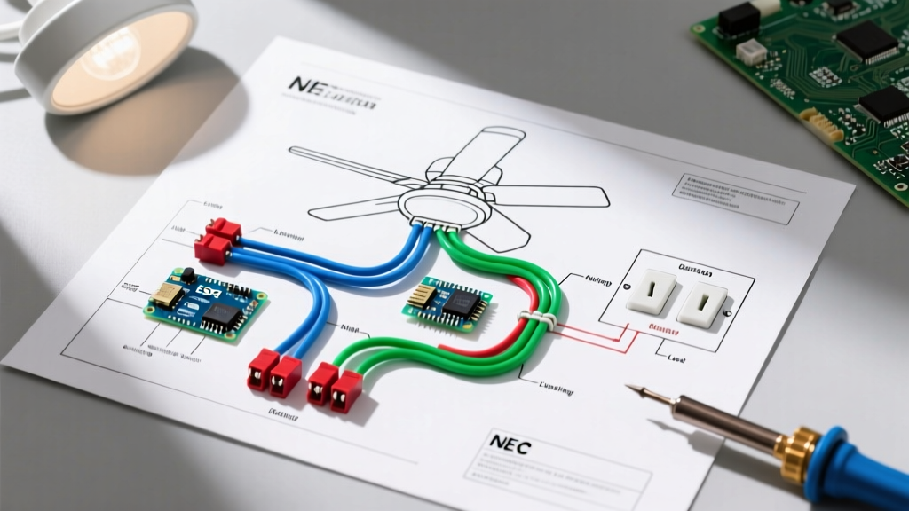
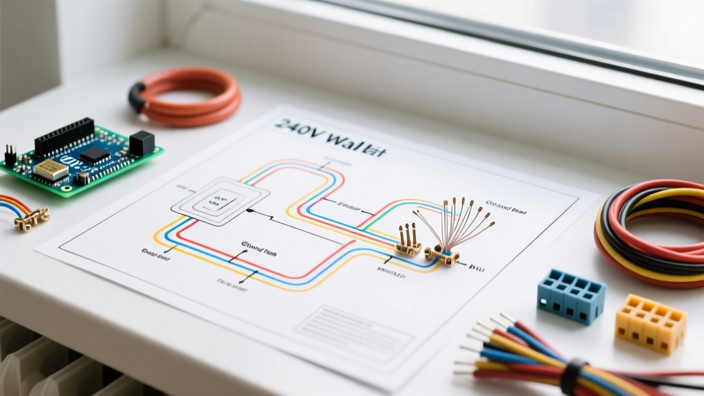
When you open the junction box of a standard 240V resistive wall heater, the wiring diagram is remarkably simple, yet frequently misunderstood by DIYers transitioning from 120V receptacle wiring.
The 240V Line-Voltage Path
A standard 240V heater requires two "hot" legs and a ground. It does not require a neutral wire. The heating element is a pure resistive load that bridges the 240V potential between the L1 and L2 bus bars of your main electrical panel.
- Black Wire (L1): Connects to one hot bus bar (120V to ground).
- White Wire (L2): In a 2-wire cable (like 12/2 NM-B), the white wire is used as the second hot leg. Crucial Step: You must wrap both ends of this white wire with black or red electrical tape, or use a permanent marker, to re-identify it as a hot conductor per NEC 200.7(C).
- Bare/Green Wire (Ground): Connects to the heater's metal chassis and the panel's ground bus bar.
Grounding and Bonding Requirements
The metal housing of the wall heater must be bonded to the equipment grounding conductor (EGC). If you are running conduit (e.g., EMT) instead of NM-B cable, the metal conduit itself can serve as the EGC, but pulling a separate 12 AWG green ground wire is highly recommended for continuity assurance and to satisfy strict local inspectors.
Thermostat Integration: Built-In vs. Smart Wi-Fi Retrofits
The most complex part of the wiring diagram for wall heater installations in 2026 is the thermostat control circuit. You have two primary routing options.
Scenario A: Built-In Line-Voltage Thermostat
Many units, like the Cadet CEH series, offer a built-in line-voltage thermostat. In this configuration, the 12/2 NM-B power feed enters the thermostat compartment first. The thermostat acts as a switch on one of the hot legs (single-pole) or both hot legs (double-pole).
- Feed L1 and L2 into the thermostat's "Line" terminals.
- Run jumper wires from the thermostat's "Load" terminals to the heater element's internal junction box.
- Safety Note: A single-pole thermostat only breaks one 120V leg. The heater will turn off, but the internal elements remain energized at 120V. For complete disconnect during maintenance, always opt for a double-pole thermostat.
Scenario B: Smart Thermostat Retrofit (Contactor Method)
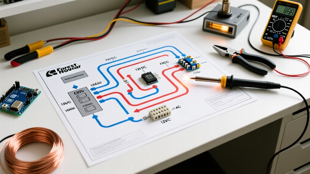
Modern smart thermostats (like Ecobee or Nest) operate on 24VAC low voltage and cannot handle 240V line-voltage loads directly. To integrate smart home controls with a 240V wall heater, you must install a 2-pole definite purpose contactor and a step-down transformer.
- The Transformer: Steps 120V down to 24VAC to power the smart thermostat.
- The Contactor: A heavy-duty relay (e.g., Packard DP20 or Honeywell R8222) wired in-line with the 240V heater circuit. The 24V smart thermostat signals the contactor coil to close the high-voltage contacts, safely activating the heater.
This setup is standard in modern electric resistance heating retrofits where homeowners want app-based scheduling without replacing the actual heating units.
Step-by-Step Installation Planning Checklist
Before purchasing materials or cutting drywall, verify the following parameters:
- Panel Capacity: Do you have two adjacent open slots in your main breaker panel for a 2-pole breaker? If not, you may need to install a tandem breaker elsewhere or upgrade your panel.
- Wire Route Length: Measure the exact route from the panel to the heater. If the run exceeds 75 feet on a 20A circuit, upsize from 12 AWG to 10 AWG to mitigate voltage drop below the recommended 3% threshold.
- Clearance Zones: Check the manufacturer's installation manual for mandatory clearances. Most wall heaters require at least 6 inches of clearance from adjacent walls and 3 feet from combustible furnishings to prevent thermal limit switch tripping.
- Thermostat Placement: Plan to mount the wall thermostat on an interior wall, away from direct sunlight, drafts, or the direct radiant heat path of the heater itself, to ensure accurate ambient temperature sensing.
Common Edge Cases and Failure Modes
The "Phantom Neutral" Mistake: The most dangerous error DIYers make when reading a wiring diagram for wall heater circuits is assuming the white wire in a 12/2 cable is a neutral. Connecting the white wire to the panel's neutral bus bar instead of the hot bus bar will result in a dead short, instantly tripping the breaker and potentially damaging the panel bus. Always re-identify the white wire as a hot conductor.
Thermal Limit Switch Tripping
If your heater turns on for 30 seconds, shuts off, and refuses to restart until it cools, the internal high-limit safety switch is tripping. This is rarely an electrical wiring fault; it is almost always an airflow restriction. Ensure the internal fan blower wheel is free of dust and that the heater's front grille is not blocked by furniture.
Shared Neutral Violations
Because a 240V wall heater does not use a neutral, you cannot share a multi-wire branch circuit (MWBC) neutral with a 120V lighting circuit on the same cable. The heater must have a dedicated 2-wire circuit (plus ground) originating from a 2-pole breaker with a common internal trip mechanism.
Final Inspection and Energization
Once the physical wiring is complete, do not immediately turn on the breaker. Use a digital multimeter to test for continuity between the hot legs and the ground to ensure no accidental shorts exist in the junction box. Once verified, energize the 2-pole breaker. You should read approximately 240V across the two hot terminals at the heater's junction box, and 120V from each hot terminal to ground. Only after confirming these voltages should you connect the thermostat and mount the heater housing to the wall can.