
The Definitive Guide to Century Dual-Voltage Motor Wiring
Century electric motors—now manufactured under the Regal Rexnord umbrella following the acquisition of A.O. Smith’s motor division—remain the industry standard for pool pumps, HVAC compressors, and heavy-duty air compressors. If you are replacing a failing motor or upgrading to a high-efficiency model in 2026, you will inevitably encounter the 115 230 volt Century electric motor wiring diagram printed on the nameplate.
Misinterpreting this diagram is the leading cause of immediate thermal overload trips, melted terminal blocks, and voided warranties. This tutorial bypasses the fluff and provides exact terminal configurations, wire gauge matrices, and failure-mode troubleshooting for Century C48, C56, and 56J frame dual-voltage motors.
Why 230V is the Superior Choice for Century Motors
While dual-voltage motors offer flexibility, wiring your Century motor for 230V (often labeled as 208-230V) is almost always the correct engineering decision for stationary appliances. According to the National Electrical Code (NEC) Article 430, motor branch circuits must be sized to handle the continuous load, and voltage drop must be managed over long runs.
When you wire a 1.5 HP Century pool pump motor (such as the popular C48K2N143B1 model) for 230V instead of 115V, you cut the amperage draw exactly in half. This yields three critical benefits:
- Reduced I²R Losses: Halving the current reduces resistive heat generation in the copper windings by 75%, extending the life of the motor's insulation class.
- Smaller Wire Gauge: You can often drop from 10 AWG to 12 AWG copper wire for runs up to 50 feet, saving roughly $0.40 per foot on THHN copper in 2026.
- Harder Starting Torque: 230V delivers superior voltage stability at the terminal block during the high-inrush locked-rotor amperage (LRA) startup phase, preventing the centrifugal switch from chattering.
Voltage Selection & Wire Sizing Matrix
Use the following reference table to select your breaker and wire gauge based on the specific Century motor horsepower and your chosen voltage. Data aligns with NEMA MG-1 standards for single-phase induction motors.
| Motor HP | 115V Amp Draw (FLA) | 230V Amp Draw (FLA) | Min Wire Gauge (115V) | Min Wire Gauge (230V) | Required Breaker |
|---|---|---|---|---|---|
| 1.0 HP | 14.0 A | 7.0 A | 12 AWG Copper | 14 AWG Copper | 20A (115V) / 15A (230V) |
| 1.5 HP | 18.6 A | 9.3 A | 10 AWG Copper | 14 AWG Copper | 25A (115V) / 20A (230V) |
| 2.0 HP | 24.0 A | 12.0 A | 8 AWG Copper | 12 AWG Copper | 30A (115V) / 20A (230V) |
Note: FLA (Full Load Amps) values are approximate for standard Century single-phase capacitor-start/induction-run motors. Always verify the exact FLA on your specific motor's nameplate.
Anatomy of the Century Terminal Block
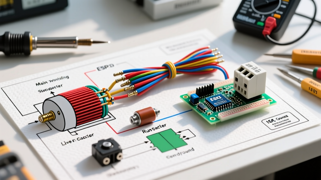
Unlike industrial 3-phase motors that feature 9 or 12 loose T-leads, modern Century appliance and pool pump motors utilize a consolidated 5-screw terminal block (labeled 1 through 5) paired with a voltage selector switch or specific jumper arrangements.
Before touching a screwdriver, identify which terminal style your Century motor uses:
- The Integrated Switch (VGreen & Modern C48): Features a physical toggle or dial on the terminal board labeled '115' and '230'. You simply set the switch and wire Line 1 and Line 2 to the designated primary screws.
- The 5-Screw Jumper Block (Legacy A.O. Smith/Century): Requires manual placement of the incoming power lines and sometimes a brass jumper to route power through the internal thermal overload protector.
Step-by-Step: Wiring for 230V (Recommended)
This procedure applies to standard 230V single-phase branch circuits (two hot legs, one ground, no neutral). Pricing for a standard replacement 1.5HP Century motor in 2026 hovers between $240 and $290, making careful installation vital to protect your investment.
1. Prepare the Conduit and Wires
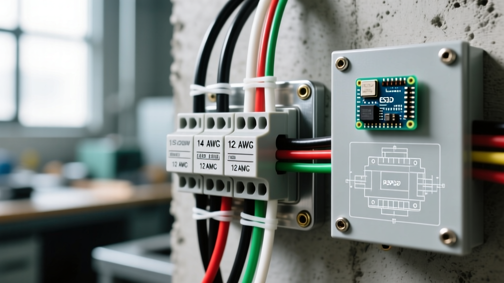
Strip exactly 3/8-inch of insulation from your 12 AWG or 14 AWG THHN wires. Do not score the copper conductor, as nicks create micro-fractures that snap under thermal expansion cycles. Crimp a #10 ring terminal or use a ferrule if your local code requires it; however, most Century terminal blocks are designed for direct bare-wire insertion under the pressure plate.
2. Configure the Voltage Selector
If your motor has a physical voltage switch, move it firmly to the 230V position. If using a 5-screw terminal block without a switch, the internal factory jumpers are typically pre-set for 230V. Do not move the factory brass jumpers unless explicitly directed by the nameplate diagram.
3. Terminate the Power Lines
- Connect Line 1 (Hot Black)
- Connect Line 2 (Hot Red/White)
- Connect the Bare/Green Ground
4. Torque the Terminals
Tighten the terminal screws to 12-15 in-lbs. A loose screw will cause high-resistance arcing, melting the plastic phenolic block within 48 hours of operation. An over-tightened screw will strip the brass threads or shear the wire strands.
Step-by-Step: Wiring for 115V (When Necessary)
Wiring for 115V is generally only recommended for portable air compressors or temporary setups where a 230V double-pole breaker is unavailable. In a 115V circuit, you are dealing with one Hot (Line), one Neutral, and one Ground.
CRITICAL WARNING: Never wire a Century motor for 115V if the run distance from the breaker panel exceeds 60 feet without upsizing the wire by two AWG gauges. The voltage drop during startup will prevent the centrifugal switch from disengaging the start capacitor, resulting in catastrophic capacitor explosion within seconds.
Terminal Connections for 115V
- Set the voltage selector switch to 115V (if equipped).
- Connect the Hot Line (Black)
- Connect the Neutral (White)
- Verify that the factory jumper between Terminal 4 and Terminal 5 is intact. This jumper completes the start-winding circuit for the lower voltage configuration.
- Terminate the Ground to the chassis green screw.
Edge Cases & Troubleshooting Failure Modes
Even with a perfect interpretation of the 115 230 volt Century electric motor wiring diagram, real-world variables can cause operational failures. Here is how to diagnose the three most common edge cases.
Failure Mode 1: Motor Hums, Shaft Spins Freely, But Won't Start
The Cause: The start capacitor has failed, or the centrifugal switch contacts are pitted. Century 1.5HP motors typically use a 110-125 µF, 125VAC start capacitor located under the rear dome cover.
The Fix: Disconnect power. Discharge the capacitor using a 20k-ohm 5-watt resistor across the terminals. Remove the capacitor and test it with a multimeter's capacitance setting. If it reads below 90 µF or shows a bulged pressure relief vent, replace it. Genuine Century replacement capacitors cost around $18 to $25.
Failure Mode 2: Thermal Overload Trips at Exactly 45 Seconds
The Cause: Voltage mismatch. You have wired the motor's terminal block for 230V, but the branch circuit is only supplying 115V. The motor attempts to produce rated horsepower by drawing double the normal current, instantly overwhelming the auto-reset thermal overload protector embedded in the stator windings.
The Fix: Verify supply voltage at the terminal block with a Fluke 117 multimeter while the circuit is energized. If you read 115V across Line 1 and Neutral, you must reconfigure the motor's terminal jumpers to the 115V layout.
Failure Mode 3: Motor Runs in Reverse (Compressors/Pumps)
The Cause: Unlike 3-phase motors where swapping any two legs reverses rotation, single-phase Century motors require swapping the start winding leads relative to the run winding.
The Fix: On a standard 9-lead NEMA setup, swap T5 and T8. On modern Century terminal blocks, rotation is often fixed by the manufacturer for specific OEM applications (like Hayward or Pentair pool pumps). If the nameplate does not show a rotation-reversal schematic, the internal wiring is hard-set, and you cannot reverse it without voiding the motor housing to physically swap internal spade connectors.
Final Commissioning Checklist
Before sealing the terminal cover and applying load, complete this final verification:
- Confirm the terminal cover gasket is seated properly to maintain the motor's IP55 weather resistance rating.
- Ensure no stray copper strands are bridging the gap between Terminal 1 and the grounded motor casing.
- Energize the circuit and measure the running amperage with a clamp meter. It should settle within 5% of the nameplate FLA within 10 seconds of startup.
By strictly adhering to the manufacturer's schematic and understanding the underlying electrical principles of dual-voltage single-phase motors, you ensure maximum efficiency, longevity, and safety for your appliance or pump system.