
Decoding the Wiring Diagram for Thermostat Installations
Transitioning from a legacy mercury-switch or basic programmable unit to a modern smart climate controller is one of the most impactful home energy upgrades you can make. However, understanding the wiring diagram for thermostat replacements is the difference between a seamless smart home upgrade and a blown control board fuse. As of 2026, advanced units like the Ecobee SmartThermostat Premium and the 4th Gen Nest Learning Thermostat demand stable 24VAC power, making proper terminal identification and circuit mapping non-negotiable.
This comprehensive appliance wiring tutorial breaks down standard HVAC control circuits, color-code conventions, and the specific edge cases that trip up both DIYers and junior technicians.
⚠️ SAFETY WARNING: Always shut off the main power to your air handler/furnace at the breaker panel before removing the old thermostat faceplate. The 24VAC control circuit is low voltage, but accidental shorts can instantly blow the 3A blade fuse on your HVAC control board or damage the transformer.
The Anatomy of a Standard HVAC Control Circuit
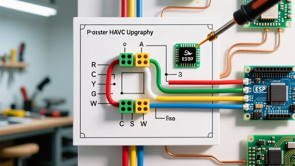
Most residential forced-air systems operate on a 24-volt alternating current (24VAC) control circuit, stepped down from 120V/240V mains via a Class 2 transformer. When you consult the wiring diagram for thermostat connections on your air handler's service panel, you will see a series of standardized terminal letters. While manufacturers generally adhere to industry color codes, always verify the wire's actual destination on the control board rather than trusting the insulation color blindly.
Standard Terminal & Color Code Matrix
| Terminal | Standard Color | Function | System Application |
|---|---|---|---|
| R / Rh / Rc | Red | 24VAC Power (Hot) | All systems. Rh (Heating) and Rc (Cooling) are used in dual-transformer setups. |
| C | Blue / Black | Common (24VAC Return) | Required for Wi-Fi/smart thermostats to maintain continuous radio power. |
| W / W1 | White | Primary Heat | Gas furnace, electric heat strips, or heat pump auxiliary heat. |
| Y / Y1 | Yellow | Primary Cooling | Sends 24VAC to the compressor contactor in the outdoor condenser. |
| G | Green | Indoor Blower Fan | Energizes the fan relay for continuous air circulation. |
| O / B | Orange / Dark Blue | Reversing Valve | Heat pumps only. Switches the system between heating and cooling modes. |
| W2 / Aux | Black / Brown | Secondary / Aux Heat | Engages electric heat strips during extreme cold or defrost cycles. |
Deep Dive: The Heat Pump Reversing Valve (O vs. B)
The most common catastrophic error when following a wiring diagram for thermostat setups in heat pump systems involves the reversing valve terminal. This valve physically shifts the refrigerant flow to change the system from heating to cooling. However, manufacturers differ on when this valve should be energized:
- Energized on Cool (O Terminal): The vast majority of manufacturers (Carrier, Trane, Lennox, Goodman) energize the reversing valve in cooling mode. The wire connects to the O terminal.
- Energized on Heat (B Terminal): Rheem and Ruud systems energize the valve in heating mode. The wire connects to the B terminal.
Failure Mode: If you wire a Rheem system to the O terminal (or vice versa), the thermostat will call for heat, but the system will blow freezing air. Modern smart thermostats prompt you to select 'O' or 'B' during the software configuration wizard to align the internal logic with your physical wiring.
The 2026 C-Wire Dilemma: Power Stealing vs. Dedicated Common
Older programmable thermostats ran on AA batteries. Early smart thermostats attempted to 'power steal' by trickling current through the heating (W) or cooling (Y) circuits without completing the relay. In 2026, with the integration of Matter-over-Thread protocols, continuous Wi-Fi, and occupancy radar sensors, power stealing is obsolete and causes 'ghost' micro-cycling of HVAC contactors.
How to Add a C-Wire Using a 24VAC Transformer
If your existing thermostat cable lacks an unused wire for the C terminal, and you cannot fish a new 18/5 or 18/8 thermostat cable through the walls, you must install a dedicated 24VAC transformer (e.g., the Honeywell AT72D1683, typically $18-$25).
- Locate Mains Power: Find a nearby 120V junction box or tap into the line side of the furnace's main power switch.
- Wire the Primary: Connect the transformer's primary leads (black and white) to 120V Hot and Neutral. Secure with wire nuts and electrical tape.
- Wire the Secondary: Connect one 24VAC secondary lead (blue) directly to the C terminal on your thermostat baseplate.
- Isolate the Secondaries: Cap off the second 24VAC lead. Do not connect it to the furnace's existing C terminal. Mixing two different 24VAC transformers on the same control circuit will result in a dead short and destroy the control board.
Troubleshooting: The Blown 3A Control Board Fuse
If you finish wiring, turn the breaker back on, and the thermostat screen remains completely dead, you have likely blown the 3-amp automotive blade fuse on the air handler's control board. This happens if the 'R' (Hot) wire accidentally brushed against the 'C' (Common) wire or the grounded metal chassis during installation.
Step-by-Step Fuse Replacement
- Turn off the HVAC breaker at the main panel.
- Remove the blower compartment access panels (the safety door switches must be depressed or bypassed to restore power for testing, but keep power OFF while working).
- Locate the main control board (usually near the blower motor).
- Find the 3A ATO (orange) or ATC (purple) blade fuse. On modern Goodman/Amana boards (e.g., B1859022), it is clearly labeled '3A'.
- Pull the fuse and inspect the internal filament. If broken or the plastic is scorched, replace it. A 10-pack of 3A fuses costs roughly $6 at any hardware store.
- Crucial Step: Before turning the power back on, double-check your thermostat baseplate wiring to ensure no stray copper strands are bridging R and C.
Authoritative References & Standards
Proper thermostat wiring must comply with local electrical codes and manufacturer schematics. For further reading on Class 2 circuit regulations and energy efficiency standards, consult the following resources:
- The U.S. Department of Energy provides comprehensive guidelines on thermostat selection and energy-saving setbacks at Energy.gov Thermostats Guide.
- For exhaustive diagnostic tables and legacy wiring schematics, InspectApedia's Thermostat Wiring Encyclopedia remains the industry gold standard for field technicians.
- To verify Energy Star compliance and utility rebate eligibility for your 2026 smart thermostat upgrade, check the EPA Energy Star Smart Thermostat database.
Frequently Asked Questions (FAQ)
Can I connect two wires to the same thermostat terminal?
While physically possible under some screw terminals, it is highly discouraged. If you have a humidifier or an electronic air cleaner that requires a signal, use an isolation relay rather than doubling up wires on the 'G' or 'W' terminals, which can cause backfeeding and erratic blower behavior.
What gauge wire is required for thermostat connections?
Standard residential thermostat wiring utilizes 18 AWG (American Wire Gauge) solid copper wire. For runs under 100 feet, 18/4 or 18/5 is standard. For runs exceeding 100 feet, or for commercial applications, upgrading to 16 AWG is recommended to prevent voltage drop across the 24VAC circuit, which can cause contactor chatter.
Why does my smart thermostat show 'No Power to Rh'?
This error usually indicates an open circuit on the 24VAC hot leg. Check the condensate overflow float switch (often located on the drain pan or inline on the PVC drain pipe). If the drain is clogged, the float switch cuts the 24VAC 'R' wire to prevent water damage, killing power to the thermostat.