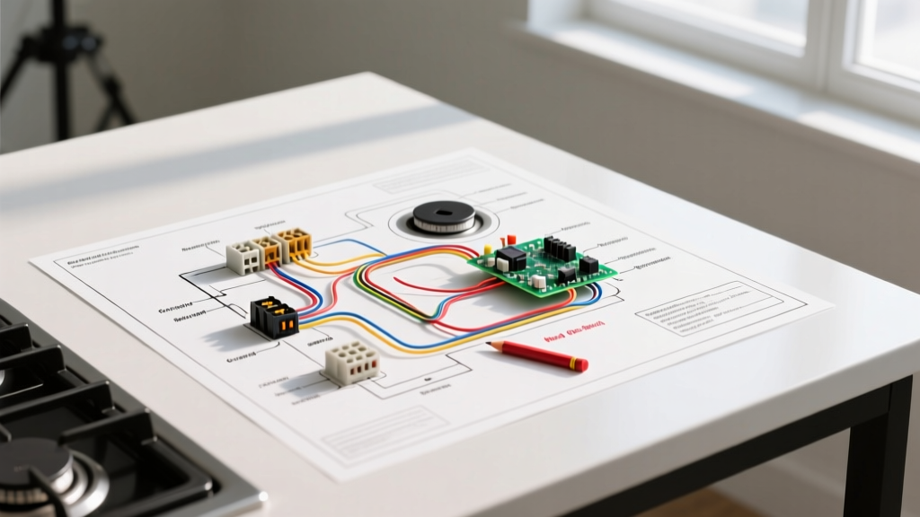

Decoding the Electric Range Wiring Diagram
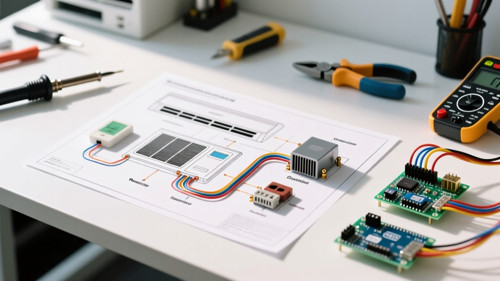
When a 240-volt electric range fails to heat, guesswork is both dangerous and expensive. The manufacturer's electric range wiring diagram is your definitive roadmap for isolating faults in high-voltage appliance circuits. Unlike a simple pictorial guide, the schematic diagram reveals the logical flow of electricity through infinite switches, thermal limiters, and control relays. By cross-referencing your multimeter readings with the schematic, you can pinpoint whether a dead burner is caused by a $15 thermal fuse or a $250 main control board.
Modern ranges, including popular 2026 models from Whirlpool, GE, and Frigidaire, utilize a split-voltage architecture. The heavy heating elements require 240 volts (derived from two 120V legs, L1 and L2), while the digital clocks, oven lights, and smart-home Wi-Fi modules operate on 120 volts (L1 to Neutral). Understanding this split is the first step in effective schematic tracing.
Schematic Symbols and Circuit Architecture
Before probing the terminal block, you must understand the standard nomenclature used in appliance schematics. Below is a reference matrix for the most common symbols you will encounter when troubleshooting an electric range.
| Symbol / Designation | Component Name | Function in the Circuit |
|---|---|---|
| L1 / L2 | Power Legs (Hot) | Supply 120V each; combined they deliver 240V to heating elements. |
| N | Neutral | Provides the 120V return path for clocks, lights, and control boards. |
| GND | Equipment Ground | Safety path to trip the breaker in case of a short to the chassis. |
| Infinite Switch | Simmerstat / Burner Control | Pulses power to the surface element via a bimetallic strip to regulate heat. |
| Thermal Limiter | High-Limit Thermostat | A non-resettable safety fuse that opens the circuit if the oven exceeds safe temps. |
The 240V/120V Split: Terminal Block Troubleshooting
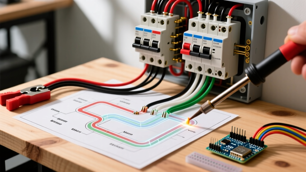
The terminal block is where the external power cord meets the internal wiring harness. In 2026, the National Electrical Code (NEC) strictly mandates 4-prong NEMA 14-50R receptacles for all new range installations, physically separating the neutral and ground paths. If you are troubleshooting an older home with a 3-prong NEMA 10-50 setup, the neutral and ground are bonded at the range's terminal block via a copper strap.
Critical Diagnostic Step: If your oven heats perfectly but the digital display is completely dead, do not replace the control board immediately. Use your wiring diagram to trace the 120V path. A loose neutral wire at the terminal block will starve the 120V control circuits while still allowing the 240V bake elements to function. Always check L1-to-N and L2-to-N for exactly 120V before condemning electronic components.
For a 50-amp circuit, the NEC requires a minimum of 8 AWG copper wire or 6 AWG aluminum wire. If you find melted terminal block lugs, it is almost always due to loose mechanical connections causing high resistance and localized arcing, rather than an overloaded circuit. Replacement 4-prong terminal blocks (like the Whirlpool W10245259) cost around $22, but you must also replace the damaged power cord and ensure torque specifications are met.
Step-by-Step Burner and Element Diagnostics
The wiring diagram allows you to isolate the exact point of failure in a heating circuit. Always disconnect power at the main breaker panel before performing continuity tests.
Testing the Infinite Switch
The infinite switch (often called a simmerstat) controls the surface burners. A common failure mode is a burner that only works on "High" or fails to heat entirely. According to the schematic, power enters the switch at L1 and exits to the element at H1 and H2.
- Continuity Test (Off Position): Place multimeter probes on L1 and H1. The reading should be OL (Open Loop / Infinite resistance).
- Continuity Test (High Position): Turn the knob to High. Probes on L1 and H1 should read near 0 ohms (closed circuit).
- Indicator Light Test: The P terminal on the switch provides 120V to the "Hot Surface" indicator light. If the burner heats but the light stays dark, test the P terminal for 120V to ground. If voltage is present, the bulb is dead; if not, the internal switch contact for the P terminal has failed.
Replacement infinite switches, such as the Whirlpool W10823692, typically retail between $75 and $110 in 2026. Always match the exact amperage rating printed on the original switch casing.
Bake and Broil Element Continuity Checks
Heating elements are simple resistive loads. The wiring diagram will show the bake element connected between L2 (via the bake relay on the control board) and L1 (via the high-limit thermostat). A standard 240V bake element (like the GE WB44T10010, priced around $55) should read between 20 and 40 ohms of resistance. A broil element will read slightly lower, typically 15 to 25 ohms.
If your multimeter reads OL, the internal nichrome wire has snapped, and the element must be replaced. If the element reads continuity but still fails to heat, use the wiring diagram to locate the inline thermal fuse. On many Frigidaire models, a blown thermal limiter (part 318004900, approx. $18) will interrupt the L2 path to the bake element while leaving the broil element fully operational.
Control Board Faults in Modern Smart Ranges
In premium 2026 models featuring convection fans, precision temperature probes, and Wi-Fi connectivity, the mechanical relays of the past have been replaced by solid-state triacs and microprocessors on the main control board. The wiring diagram for these units is highly complex, featuring low-voltage DC ribbon cables communicating with the user interface (UI) board.
If the schematic shows that the bake relay receives 120V on its coil but fails to output 240V to the element, the board's internal triac has shorted or opened. Main control boards, such as the Frigidaire 5304518661, cost between $190 and $280. Before ordering a replacement, verify that the door latch switch assembly is functioning. The wiring diagram will show the door switch in series with the self-clean and bake circuits; a misaligned door latch will trick the logic board into inhibiting the heating relays as a safety precaution.
Safety Protocols and Code Compliance
Troubleshooting 240-volt appliances carries a severe risk of arc flash and electrocution. The Consumer Product Safety Commission (CPSC) strongly advises against live-voltage probing unless you are a certified technician with Category III (CAT III) or higher rated test equipment. For DIYers, the "dead testing" method—using the wiring diagram to perform continuity and resistance checks with the breaker locked out—is the safest and most reliable approach.
Furthermore, any repairs involving the power cord or terminal block must comply with the National Electrical Code (NEC) Article 250, which dictates proper grounding and bonding of major appliances. Never remove the equipment grounding conductor to solve a nuisance tripping issue; this is a severe life-safety hazard. For more on appliance efficiency and electrical standards, the U.S. Department of Energy provides excellent guidelines on ensuring your repaired range meets modern energy consumption benchmarks.
Frequently Asked Questions
Why does my oven light work, but the bake element won't heat?
The oven light operates on a 120V circuit (L1 to Neutral), while the bake element requires 240V (L1 to L2). If the light works, your neutral is intact. The fault lies in the 240V path. Trace the wiring diagram from the L2 terminal, through the main control board's bake relay, and down to the element. A failed relay or a blown inline thermal fuse is the most common culprit.
Can I use a 3-prong cord on a new 2026 electric range?
While you can physically wire a 3-prong cord to a modern range using the provided grounding strap, the NEC prohibits installing new 3-prong NEMA 10-50 receptacles. If your home has a modern 4-prong NEMA 14-50R outlet, you must use a 4-prong cord and remove the neutral-to-ground bonding strap on the range's terminal block to prevent dangerous neutral current from flowing through the chassis.
How do I test a convection fan motor using the diagram?
Locate the convection motor on the schematic. It is typically a 120V AC motor powered by a dedicated relay on the control board. Disconnect the wire harness at the motor terminals and test the motor windings for resistance (usually 20-50 ohms). If the motor reads open, it is dead. If the motor tests fine, use the diagram to verify that the control board is sending 120V to the motor harness during the convection bake cycle.