
The Critical Role of Wire Gauge and Color Codes in Solar PV
When interpreting a wiring diagram for solar system installations, the most common point of failure isn't the inverter or the charge controller—it's undersized or improperly color-coded cabling. A solar photovoltaic (PV) system operates in two distinct electrical environments: the high-current, low-voltage DC side (panels to inverter/batteries) and the standard AC side (inverter to the main service panel). Mixing up the wire gauge or ignoring National Electrical Code (NEC) color standards doesn't just risk system inefficiency; it creates severe fire hazards.
As of 2026, with residential solar arrays frequently pushing 10kW to 15kW capacities and battery backups becoming standard, understanding the exact American Wire Gauge (AWG) requirements and insulation types is non-negotiable. This guide breaks down the technical specifications you need to execute a safe, code-compliant solar wiring diagram.
Decoding the Wiring Diagram: DC vs. AC Circuits
A complete solar wiring diagram is essentially two separate schematics joined at the inverter. The DC side requires specialized UV-resistant wiring and strict voltage drop management, while the AC side must integrate seamlessly with your home's existing split-phase 120V/240V architecture.
- DC Source Circuit: Connects solar modules to the combiner box or charge controller. Typically operates between 30V and 600V DC.
- DC Battery Circuit: Connects the battery bank to the inverter/charger. This is the highest current segment of the system, often requiring 2/0 AWG to 4/0 AWG copper.
- AC Output Circuit: Connects the inverter to the home's breaker panel via a dedicated backfed breaker or line-side tap.
NEC Color Code Standards for Solar PV Systems
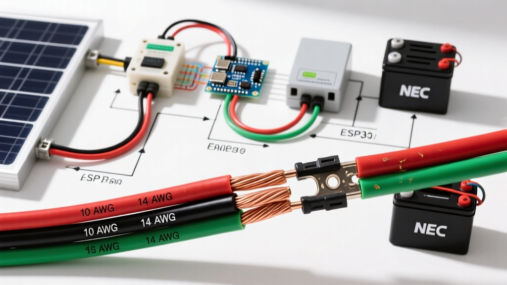
The NEC strictly dictates wire coloring to prevent catastrophic cross-wiring. According to the NFPA NEC guidelines (specifically Articles 200, 210, and 690), solar installers must adhere to the following color matrices. Note that DC and AC color codes are fundamentally different.
DC Side Color Codes (Solar Panels & Batteries)
| Conductor Function | Ungrounded System | Grounded System (Legacy/Specific) |
|---|---|---|
| Positive (+) | Red (or Black with Red tape) | Red |
| Negative (-) | Black (or White with Black tape) | White or Gray (Must be marked) |
| Equipment Ground | Bare Copper, Green, or Green/Yellow Stripe | |
Expert Note: Modern transformerless inverters require ungrounded DC arrays. Therefore, you should almost exclusively use Red for Positive and Black for Negative on the roof, reserving White/Gray strictly for AC neutral.
AC Side Color Codes (Inverter to Main Panel)
| Conductor Function | 120V Single Phase | 240V Split Phase |
|---|---|---|
| Line 1 (Hot) | Black | Black |
| Line 2 (Hot) | N/A | Red |
| Neutral | White or Gray | |
| Equipment Ground | Bare Copper or Green | |
Wire Gauge Selection: Beating Voltage Drop
Sizing wire based solely on ampacity (the maximum current a wire can carry before melting) is a rookie mistake. In solar design, voltage drop is the governing metric. The industry standard, supported by the U.S. Department of Energy's solar planning resources, dictates a maximum voltage drop of 1.5% to 2% for DC strings and 3% for AC runs.
The Voltage Drop Formula
To calculate the exact AWG needed for your wiring diagram for solar system layouts, use the standard single-phase voltage drop formula:
VD = (2 × K × I × L) / CM
Where:
VD = Voltage Drop
K = Resistivity constant (12.9 for Copper at 75°C)
I = Current in Amps
L = One-way length of the wire in feet
CM = Circular Mils of the wire gauge
Real-World Calculation Example
Imagine a string of three 440W bifacial panels wired in series. The string produces 11.5 Amps at 123V DC. The distance from the roof combiner box to the inverter in the garage is 80 feet. We want a voltage drop under 2% (2.46V).
- Using 12 AWG (CM = 6530): VD = (2 × 12.9 × 11.5 × 80) / 6530 = 3.63V (2.95% Drop) — Fails the 2% rule.
- Using 10 AWG (CM = 10380): VD = (2 × 12.9 × 11.5 × 80) / 10380 = 2.28V (1.85% Drop) — Passes.
In this scenario, your wiring diagram must specify 10 AWG PV Wire, even though 12 AWG could technically handle the 11.5A thermal load.
Insulation Types: PV Wire vs. THHN vs. USE-2
A common edge case that causes system failures within 3 to 5 years is using indoor-rated wire on the roof. As of 2026, specialized solar wire costs roughly $0.95 to $1.30 per foot for 10 AWG, but cutting corners here violates NEC Article 690.31.
| Wire Type | UV Resistance | Temperature Rating | Application Zone |
|---|---|---|---|
| PV Wire | Excellent (XLPE Insulation) | 90°C Wet / 120°C Dry | Exposed roof runs, module pigtails |
| USE-2 | Good | 90°C Wet / Dry | Roof runs (but lacks VW-1 flame rating) |
| THHN / THWN-2 | None (Degrades in sunlight) | 90°C Dry / 75°C Wet | Strictly inside conduit or indoors |
Failure Mode Alert: If you run THHN wire in a roof conduit, you must apply NEC 310.15 temperature derating. A conduit sitting in direct summer sun on a dark shingle roof can reach internal temperatures of 140°F to 160°F (60°C to 71°C). At these temperatures, a 10 AWG THHN wire's ampacity drops from 30A down to roughly 17A, potentially causing the insulation to melt and short-circuit against the metal conduit.
Quick-Reference Solar Wire Sizing Matrix (Copper)
Use this matrix as a baseline for your wiring diagram. These values assume a 75°C termination temperature rating (standard for most modern solar inverters and breakers) and an ambient temperature of 30°C (86°F).
| Max Current (Amps) | Minimum AWG (Ampacity) | Recommended AWG (For 50ft Run @ <2% Drop) | Conduit Fill (Max Wires in 1/2" EMT) |
|---|---|---|---|
| 15A (Microinverter AC) | 14 AWG | 10 AWG | 9 |
| 20A (String Inverter AC) | 12 AWG | 8 AWG | 9 |
| 30A (DC Combiner Output) | 10 AWG | 6 AWG | 9 |
| 50A (Battery Charge/Discharge) | 8 AWG | 3 AWG | 5 |
| 100A (Main Inverter Feed) | 3 AWG | 1/0 AWG | 3 |
| 200A+ (Heavy Surge/Battery Bank) | 2/0 AWG | 4/0 AWG | 1 (Requires 1"+ Conduit) |
Step-by-Step: Sizing Battery to Inverter Cables
Battery cables experience massive surge currents. A 3000W 24V inverter will draw 125A continuously, but may surge to 250A+ for motor startups.
- Calculate Continuous Load: 3000W / 24V = 125A.
- Apply NEC 125% Safety Factor: 125A × 1.25 = 156.25A.
- Select Base AWG: 156A requires a minimum of 2/0 AWG copper (rated for 175A at 75°C).
- Verify Voltage Drop: For a 5-foot run, 2/0 AWG yields a negligible 0.15V drop (0.6%).
- Final Spec: Use 2/0 AWG stranded, pure copper welding cable or THHN in flexible conduit, terminated with heavy-duty lugs torqued to the manufacturer's exact specification (usually 15-20 ft-lbs).
Frequently Asked Questions
Can I use standard Romex (NM-B) for outdoor solar panel wiring?
Absolutely not. Romex is rated for dry, indoor, protected locations only. The PVC jacket will degrade rapidly under UV exposure, and it lacks the wet-location ratings required for outdoor solar arrays. You must use PV Wire or THWN-2 routed inside UV-rated rigid PVC or metal conduit.
What color should the grounding electrode conductor (GEC) be?
According to NEC Article 250.119, the equipment grounding conductor can be bare, covered, or insulated. If insulated, it must be green or green with one or more yellow stripes. For the Grounding Electrode Conductor (connecting the ground bus to the earth ground rod), bare copper is the industry standard and perfectly legal, though some inspectors prefer green insulation for easy identification.
Do I need to update my wiring diagram if I add more panels in series?
Yes. Adding panels in series increases the DC voltage but keeps the current (Amps) the same. While your wire gauge might not need to change for ampacity, you must verify that the total open-circuit voltage (Voc), corrected for your region's lowest historical winter temperature, does not exceed the inverter's maximum DC input rating (usually 500V or 600V) or the insulation rating of your PV wire (rated for 600V or 1000V).