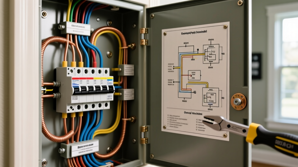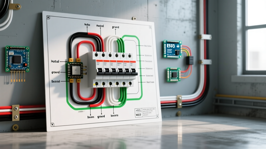

When installing or servicing a modern central air conditioning system, interpreting the wiring diagram for AC compressor circuits is only half the battle. The true test of a safe, code-compliant installation lies in how that low-voltage control logic and high-voltage power routing integrate with your main electrical panel. As of 2026, with the industry-wide shift toward R-454B and R-32 refrigerants and the proliferation of variable-speed inverter compressors, electrical demands and inrush current profiles have evolved significantly. This guide bridges the gap between the schematic taped inside your condenser access panel and the breakers sitting in your main service panel.
Decoding the Wiring Diagram for AC Compressor Circuits
The schematic provided by manufacturers like Carrier, Trane, or Lennox typically divides the electrical system into two distinct zones: the power circuit (240V) and the control circuit (24V). Understanding this separation is critical before you ever pull wire from your panel.
The Power Circuit (240V)
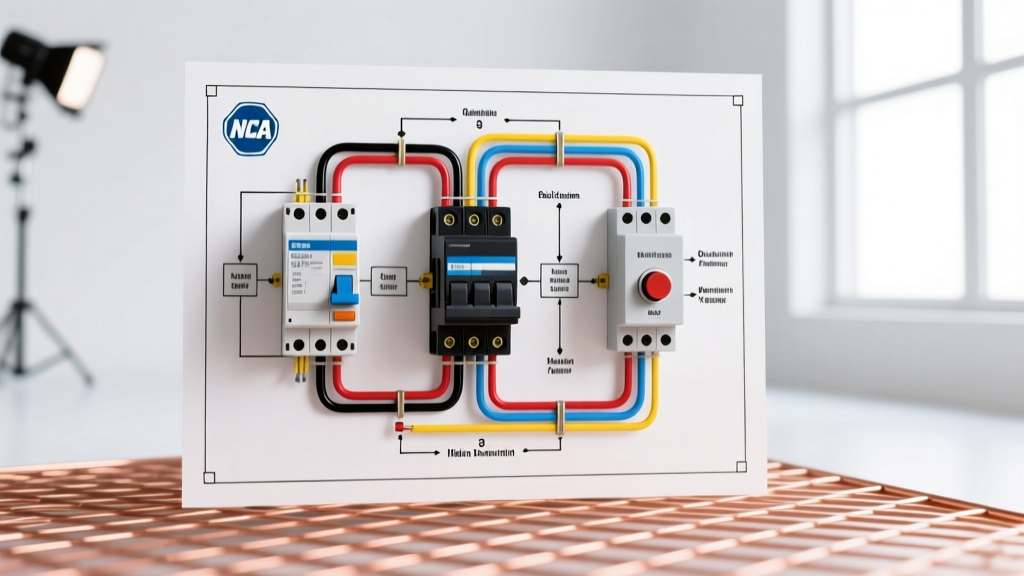
Tracing the high-voltage path on your wiring diagram, you will see the 240V lines (L1 and L2) entering the unit and terminating at the main contactor. From the contactor's load side (T1 and T2), the power splits. One path feeds the compressor terminals (C, R, and S for single-phase units), while the other feeds the condenser fan motor. Crucially, the diagram will show a dual run capacitor wired in parallel to provide the necessary phase shift for the compressor's start winding. If you are wiring a newer variable-speed inverter unit, the diagram will instead route L1 and L2 into an enclosed inverter drive board, which then outputs 3-phase DC to the compressor.
The Control Circuit (24V)
The control side originates from a step-down transformer (usually located in the indoor air handler) or a dedicated 24V transformer in the outdoor unit. This circuit powers the contactor coil. When your smart thermostat calls for cooling, it closes the circuit between the 'Y' and 'C' terminals, energizing the coil and pulling the high-voltage contacts closed.
Code Insight: According to NFPA 70 (NEC) Article 440, the branch-circuit conductors supplying the air conditioner must be sized based on the unit's Minimum Circuit Ampacity (MCA), while the overcurrent protective device (breaker) is sized based on the Maximum Overcurrent Protection (MOCP) rating listed on the nameplate.
2026 NEC Panel Breaker & Wire Gauge Matrix
Sizing your breaker and wire gauge incorrectly is the most common cause of nuisance tripping and potential fire hazards. The table below provides a baseline matrix for standard single-phase, 240V residential central air systems. Always defer to the specific MCA and MOCP values on your unit's data plate, as high-efficiency models may draw less current than legacy units of the same tonnage.
| Unit Tonnage | MCA (Amps) | MOCP (Amps) | Breaker Type & Model Example | Copper Wire Gauge (THHN/THWN-2) | Min. Conduit Size |
|---|---|---|---|---|---|
| 1.5 Ton | 12.0A | 15A / 20A | 15A HACR (e.g., Eaton BR215) | 12 AWG | 1/2 inch |
| 2.0 Ton | 15.5A | 20A / 25A | 20A HACR (e.g., Square D QO220) | 12 AWG | 1/2 inch |
| 3.0 Ton | 21.0A | 30A / 35A | 30A HACR (e.g., Siemens Q230) | 10 AWG | 1/2 inch |
| 4.0 Ton | 28.0A | 40A / 45A | 40A HACR (e.g., Square D QO240) | 8 AWG | 3/4 inch |
| 5.0 Ton | 34.5A | 50A / 60A | 50A HACR (e.g., Eaton BR250) | 6 AWG | 3/4 inch |
Note on Pricing: Due to global copper market fluctuations in 2026, a 250-foot spool of 8 AWG THHN copper wire averages between $130 and $160. Always calculate your exact run length plus 10% for waste before purchasing.
Step-by-Step: Main Panel to Outdoor Disconnect
Routing power from your main service panel to the outdoor compressor requires strict adherence to physical installation standards. Follow this sequence to ensure a robust, weather-resistant connection.
- Panel Termination: Install the appropriate 2-pole HACR (Heating, Air Conditioning, and Refrigeration) rated breaker. Strip exactly 3/4 inch of insulation from your THHN conductors. Torque the breaker terminal screws to the manufacturer's specification (typically 25 to 35 in-lbs for 10-6 AWG wire) using a calibrated torque screwdriver to prevent thermal loosening over time.
- Conduit Routing: Use Schedule 80 PVC for underground runs or EMT (Electrical Metallic Tubing) for surface mounts. When transitioning from the rigid conduit to the outdoor disconnect box or the condenser whip, use Liquid-Tight Flexible Metal Conduit (LFMC) to absorb compressor vibration and prevent moisture ingress.
- Outdoor Disconnect: Install a 60-Amp non-fused pullout disconnect box within sight of the condenser (NEC 440.14). Land the L1 and L2 lines on the line-side lugs. Connect the bare copper equipment grounding conductor to the dedicated ground bus bar, ensuring it is bonded to the enclosure.
- The Condenser Whip: Use a pre-assembled, UV-resistant LFMC whip. Land T1 and T2 on the contactor lugs. Crucially, verify that the ground wire is securely fastened to the unit's chassis ground lug, not just left floating in the junction box.
Common Wiring Failures & Edge Cases
Even experienced DIYers and junior technicians make critical errors when translating the wiring diagram into physical connections. Avoid these specific failure modes:
- Using Standard Breakers Instead of HACR: Standard thermal-magnetic breakers may trip prematurely under the high inrush current (Locked Rotor Amps) of an AC compressor starting up. HACR breakers feature modified magnetic trip curves designed specifically for motor loads.
- Ignoring Voltage Drop on Long Runs: The NEC recommends a maximum voltage drop of 3% for branch circuits. If your condenser is located more than 120 feet from the main panel, you must upsize your wire gauge by one step (e.g., using 8 AWG instead of 10 AWG for a 3-ton unit) to prevent compressor overheating and premature failure.
- Control Wire Interference: When running the 18/5 or 18/8 low-voltage thermostat cable alongside the 240V power lines in the same trench, maintain a minimum 12-inch separation or use a physical barrier. Failing to do so can induce electromagnetic interference (EMI), causing erratic behavior in modern communicating thermostats.
Frequently Asked Questions
Do I need a neutral wire for a standard AC compressor?
No. Standard residential split-system air conditioners operate on 240V single-phase power, which requires two hot legs (L1 and L2) and an equipment ground. A neutral wire is only required if the outdoor unit contains 120V accessories, such as a crankcase heater or a dedicated 120V GFCI convenience receptacle mounted on the unit.
Why does my wiring diagram show a 'hard start kit'?
If your wiring diagram includes a hard start kit (a start capacitor paired with a potential relay), it is typically an aftermarket addition or a factory option for units operating in areas with low line voltage. It provides an extra phase-shifted torque boost to help aging compressors overcome high head pressures during startup, reducing the strain on your panel breaker.
Can I use aluminum wire for the AC compressor circuit?
While the Department of Energy and NEC permit the use of AA-8000 series aluminum alloy wire for feeders and large branch circuits, it is highly discouraged for the final whip connection to the condenser. Aluminum is more susceptible to thermal expansion and contraction, which can lead to loose terminations at the vibrating contactor lugs. Stick to copper THHN/THWN-2 for the entire branch circuit to ensure long-term reliability.
For further reading on energy efficiency standards and electrical requirements for modern HVAC systems, consult the EPA Energy Star guidelines for central air conditioners. Always pull the necessary local permits and have your final panel connections inspected by a licensed authority having jurisdiction (AHJ).