
Introduction: The Intersection of Legacy Iron and Modern Electronics
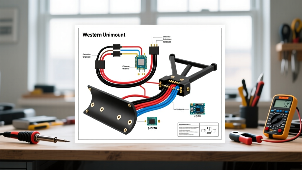
The Western Unimount remains one of the most robust and reliable snow plow platforms ever engineered. However, when you pull up a wiring diagram for a Western Unimount plow, you are looking at a system originally designed in an era before vehicles featured highly sensitive, multiplexed CAN-bus networks. As we navigate the 2026 winter season, installing or refurbishing a Unimount on a modern heavy-duty truck requires strict adherence to electrical safety codes, SAE standards, and precise voltage management. A poorly executed harness doesn't just risk a blown fuse; it can send a back-EMF spike directly into your truck's Body Control Module (BCM), resulting in thousands of dollars in dealership repairs.
This guide transcends basic pinout charts. We will dissect the wiring architecture from a strict safety and code compliance perspective, ensuring your high-amperage motor circuits, control harnesses, and lighting adapters meet the rigorous demands of modern commercial vehicle standards.
The High-Amperage Motor Circuit: SAE Compliance and Voltage Drop
The heart of the Unimount system is its hydraulic pump motor—typically a Prestolite or Fenner unit. Under heavy load, such as when lifting a fully loaded 8.5-foot steel moldboard, these motors can draw 120 to 140 amps continuously, with stall currents briefly exceeding 180 amps. The SAE International standards dictate strict guidelines for wire insulation and voltage drop in high-current DC automotive applications.
Wire Gauge Selection and SAE J1128 Standards
Never use standard copper building wire (THHN) for under-hood plow routing. You must use SAE J1128 Type SGX or SXL cross-linked polyethylene (XLPE) insulated battery cable, which is rated for under-hood temperatures up to 125°C and resists abrasion from engine vibration.
| One-Way Cable Length | Max Continuous Amps | Minimum Wire Gauge (SGX) | Recommended Wire Gauge (SGX) | Expected Voltage Drop |
|---|---|---|---|---|
| Under 6 Feet | 140A | 2 AWG | 1/0 AWG | < 0.25V |
| 6 to 10 Feet | 140A | 1/0 AWG | 2/0 AWG | < 0.35V |
| 10 to 15 Feet | 140A | 2/0 AWG | 3/0 AWG | < 0.45V |
Fuse Sizing and Placement Code Requirements
Per commercial vehicle electrical best practices, the main overcurrent protection device must be installed within 18 inches of the positive battery terminal. For a Western Unimount, a 150A ANL fuse or a 150A Class T fuse is mandatory. Avoid automotive maxi-fuses for the main feed, as their interrupt capacity (AIC) is insufficient to safely clear a dead short on a high-output alternator system without melting the fuse housing.
Solenoid Selection: Intermittent vs. Continuous Duty
A critical failure mode in Unimount wiring is the use of an intermittent-duty solenoid (like those found in winches or starter circuits) for the plow motor. Plowing requires holding the motor engaged for up to 15–20 seconds per lift cycle, often repeatedly in rapid succession.
Expert Specification: Always specify a continuous-duty solenoid, such as the Trombetta 974-1211-011 or the White-Rodgers 586-902. These units feature heavy-duty copper windings and silver-alloy contacts rated for 200A make and 150A carry, preventing the internal contacts from welding together during high-inrush stall events.
Wire the solenoid trigger circuit using a minimum of 12 AWG TXL wire, protected by a 10A inline ATO fuse located at the power source. This isolates the control cab switch from the heavy motor current.
Control Harness Architecture and ECM Protection
The classic Unimount utilizes a 2-plug system: a 2-pin power connector and a 9-pin (or 11-pin) control connector. When reviewing the official Western Plows wiring schematics, the control circuit relies heavily on the vehicle's chassis ground. This is where modern truck compatibility issues arise.
The Ground Loop Hazard on Modern Trucks
Trucks manufactured from 2020 onward utilize the chassis as a ground return for sensitive CAN-bus sensors. If your Unimount control valves draw heavy return current through a poor chassis ground, the voltage differential can backfeed into the truck's Engine Control Module (ECM) or BCM, triggering phantom check-engine lights or frying the module entirely.
The Compliance Solution: Run a dedicated 10 AWG ground wire from the plow's control harness ground pin directly to the truck's engine block or the negative battery terminal. Do not rely on the truck's frame or bed bolts for the control circuit ground return. Use a solid-state relay module in the cab to trigger the solenoid, ensuring complete galvanic isolation between the plow's inductive loads and the truck's delicate multiplexed wiring.
Lighting Integration and FMVSS 108 Compliance
Federal Motor Vehicle Safety Standard (FMVSS) 108 governs all automotive lighting. When the plow is mounted, it must fully obscure and replace the truck's headlights, turn signals, and parking lights. The NHTSA lighting regulations require that plow lighting matches the photometric output of the original vehicle equipment.
Headlight Adapter Wiring and Diode Isolation
Most Unimount setups use HB5 (9007) to H11 or HB3 (9005) headlight adapters. To comply with safety codes and prevent backfeed into the truck's lighting control module:
- Install Isolation Diodes: Place high-amperage (minimum 10A) blocking diodes on the turn signal and parking light feeds. This prevents the plow's LED or halogen draw from trickling back into the truck's BCM, which can cause hyper-flashing or BCM shutdown.
- Use Relay-Driven Headlight Harnesses: For high-draw H11 or 9005 halogen bulbs, wire a dedicated headlight relay harness. Trigger the relays using the truck's low-current headlight signal wire, and pull the heavy current directly from the plow's isolated power feed.
- Seal All Connections: Every exterior splice must be sealed with dual-wall adhesive-lined heat shrink. Standard electrical tape will fail within one season due to UV exposure, road salt, and thermal cycling.
Step-by-Step Safety and Compliance Inspection Checklist
Before energizing the system for the first time, run through this mandatory compliance checklist to ensure your wiring diagram for a Western Unimount plow has been executed safely:
- Main Power Feed: Verify 1/0 AWG (or larger) SAE J1128 SGX wire is used from the battery to the solenoid, and from the solenoid to the plow motor.
- Overcurrent Protection: Confirm a 150A ANL or Class T fuse is installed within 18 inches of the positive battery post.
- Motor Ground: Inspect the heavy ground strap connecting the plow motor casing to the truck's engine block. Ensure it is free of paint, rust, and undercoating.
- Control Ground Isolation: Verify the control harness ground is wired directly to the battery negative or engine block, bypassing the truck's sheet metal.
- Connector Weatherproofing: Apply a liberal coat of Permatex 22058 dielectric grease to all 9-pin control and 2-pin power connectors to prevent galvanic corrosion and moisture ingress.
- Lighting Backfeed Test: With the truck running and plow connected, unplug the plow. Ensure the truck's headlights and turn signals immediately revert to normal operation without BCM error codes.
Common Failure Modes and Edge Case Troubleshooting
Even with a perfect schematic, environmental factors introduce edge cases. Here is how to diagnose the most common safety and performance failures in Unimount wiring:
Solenoid Chatter and Voltage Drop
Symptom: The solenoid clicks rapidly when the lift button is pressed, but the motor doesn't engage.
Diagnosis: This is almost always a voltage drop issue on the trigger circuit, not a bad solenoid. Under load, the trigger wire is dropping below 9V. Check for corroded firewall bulkhead connectors or undersized trigger wiring (smaller than 12 AWG). Measure voltage directly at the solenoid's 'S' terminal while the button is depressed; it must remain above 10.5V.
Melted 2-Pin Power Connectors
Symptom: The plastic housing of the 2-pin motor power plug is melted or charred.
Diagnosis: High resistance at the pin connection. This occurs when the pins are not fully seated, or when the tension springs inside the female connector have fatigued. Replace both the truck-side and plow-side 2-pin connectors with heavy-duty, silver-plated terminal upgrades. Never sand the pins to clean them; this removes the corrosion-resistant plating and accelerates future oxidation.
Conclusion
Executing a safe, code-compliant installation based on a wiring diagram for a Western Unimount plow requires looking beyond the basic lines on a page. By respecting SAE wire standards, isolating modern vehicle CAN-bus systems from heavy inductive loads, and strictly adhering to FMVSS 108 lighting rules, you ensure that your plow operates reliably through the harshest winter conditions without compromising the electrical integrity of your truck. Proper electrical hygiene is the ultimate safety feature.