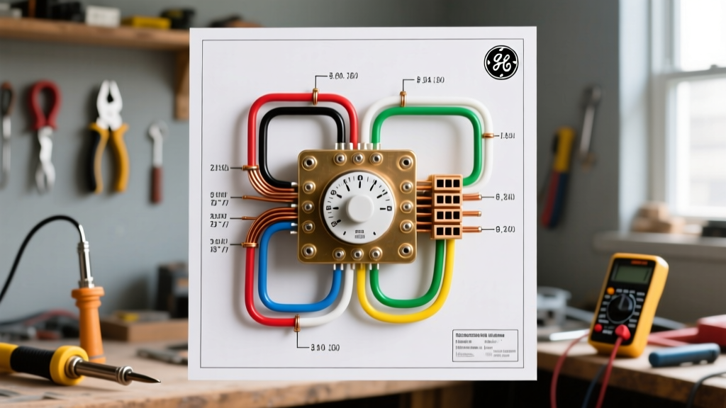

Understanding the GE Electric Dryer Timer Wiring Diagram
When diagnosing a malfunctioning clothes dryer, the timer is often the central nervous system of the appliance. For technicians and advanced DIYers, interpreting a GE electric dryer timer wiring diagram requires more than just tracing lines; it demands a thorough understanding of wire gauge specifications and standardized color codes. General Electric (GE) dryers, such as the popular GTD33EASKWW model, utilize a 240-volt split-phase system. This means the timer must safely route both high-amperage 240V power to the heating element and low-amperage 120V power to the timer motor and control solenoids.
In 2026, replacement timers like the GE WE4M533 or WE04X24550 typically cost between $45 and $85. However, misinterpreting the wire gauge or color code on the schematic can lead to catastrophic failure, melted harnesses, or blown 30-amp double-pole breakers. This guide breaks down the exact wire gauges, color designations, and schematic reading techniques required to safely service GE dryer timer circuits.
Standard Wire Color Codes in GE Dryer Schematics
GE appliance schematics use a standardized alpha-numeric code to denote both the color and the gauge of the wire. For instance, a wire labeled 14-R indicates a 14 AWG Red wire, while 18-BU indicates an 18 AWG Blue wire. Understanding this legend is critical before touching a multimeter to the timer terminals.
| Wire Color | Schematic Code | Primary Function | Standard Gauge | Voltage / Amperage |
|---|---|---|---|---|
| Red | R | L1 Line (Main 120V Leg) | 14 AWG or 10 AWG | 120V / Up to 30A |
| Black | BK | L2 Line (Secondary 120V Leg) | 14 AWG or 10 AWG | 120V / Up to 30A |
| White | W | Neutral (120V Control Return) | 14 AWG | 120V / < 5A |
| Orange | O | Drive Motor Run/Start | 16 AWG or 18 AWG | 120V / 3A - 6A |
| Blue | BU | Timer Motor / Advance Circuit | 18 AWG | 120V / < 1A |
| Yellow | Y | Heater Element Switched Leg | 10 AWG | 240V / 15A - 20A |
| Green/Bare | GR | Equipment Grounding | 10 AWG or Bare | 0V (Fault Path) |
Line vs. Load: Tracing the 240V Split
A common point of confusion when reading a GE electric dryer timer wiring diagram is how 240V is utilized. The dryer receives 240V from the panel via two 120V legs (L1 and L2). The timer does not 'see' 240V across its internal control motor. Instead, the timer motor operates on 120V, typically bridging L1 (Red) and the Neutral (White) or a dedicated L2 return path. The 240V potential is only realized when the timer's internal cam switches close, allowing L1 to pass through the timer to the heating element, while L2 feeds the element directly or via the operating thermostat.
Wire Gauge Specifications: Control vs. Heat Circuits
According to the National Electrical Code (NEC), wire ampacity must match the overcurrent protection device and the specific load. GE dryers strictly adhere to these gauging rules, which are reflected in their wiring diagrams.
- 10 AWG Wire (30 Amp Capacity): Used exclusively for the high-current heating element circuit and the main power feed from the terminal block. If your diagram shows a 10 AWG wire routing through the timer (rare, but present in some older mechanical models), it is strictly acting as a pass-through switch for the heater element. Standard 10 AWG THHN copper wire costs roughly $0.25 to $0.35 per foot in 2026.
- 14 AWG Wire (15 Amp Capacity): The workhorse of the dryer's 120V control circuits. It feeds the drive motor, the timer motor, and the moisture sensors. It is thick enough to prevent voltage drop over the short distances inside the dryer cabinet while remaining flexible enough for the wire harness.
- 18 AWG Wire (Low Ampacity): Used for low-draw components like the timer advance motor, LED indicator lights, and electronic control board signals. These circuits draw less than 1 amp, making 18 AWG perfectly safe and highly flexible.
Expert Warning: Never substitute 18 AWG wire for a 14 AWG circuit on a GE dryer schematic. If a 14 AWG Red wire (L1 feed to the motor) is damaged, replacing it with 18 AWG wire will cause the wire to act as a fuse, melting the insulation and creating a severe fire hazard before the 30A breaker trips.
Step-by-Step: Reading the WE4M533 Timer Schematic
The GE WE4M533 is one of the most ubiquitous mechanical timers in GE electric dryers. Let us break down how to read its specific wiring diagram and terminal designations.
- Identify the Power Input (Terminal TM): The schematic will show a Red (14-R) wire entering the timer at terminal TM. This is your L1 120V feed from the terminal block.
- Trace the Timer Motor (Terminal TC): A Blue (18-BU) or White (14-W) wire will route from the timer motor winding back to the neutral or L2 side. When the dryer is turned on, 120V is applied across TM and TC, causing the timer to advance.
- Locate the Heater Switch (Terminal H): In the 'Timed Dry' or 'Auto Dry' cycles, the internal cam closes the contact between TM and H. The schematic shows a Yellow or Red wire exiting terminal H, routing through the high-limit thermostat and into the heating element.
- Verify the Motor Centrifugal Switch Interlock: GE diagrams often show the timer's heater circuit passing through the drive motor's centrifugal switch. This is a critical safety feature: if the drive motor fails (and the drum stops spinning), the centrifugal switch opens, cutting power to the heater to prevent a fire. The diagram will denote this with a dashed line or a specific node labeled 'MTR SW'.
Common Failure Modes & Multimeter Testing
When a GE dryer fails to heat or the timer will not advance, the wiring diagram is your roadmap for isolation testing. Using a True-RMS multimeter (like the Fluke 117), you can verify the circuit integrity.
- Timer Motor Burnout: Disconnect the Blue (18-BU) wire from the timer motor. Set your multimeter to Ohms (Ω). Place the probes on the timer motor terminals. A healthy GE timer motor should read between 10,000 and 15,000 ohms. A reading of 'OL' (Open Line) indicates a burnt-out internal winding, requiring a full timer replacement.
- Internal Contact Pitting: Over time, the 240V heater contacts inside the timer can pit and arc, increasing resistance. With the dryer unplugged, set the timer to 'Timed Dry'. Test for continuity between the L1 input terminal and the Heater output terminal. You should read near 0.0 ohms. If you read high resistance (e.g., 5+ ohms), the contacts are degraded.
- Stripped Cam Gears: If the timer motor hums but the dial does not turn, the internal plastic cam gears are likely stripped. This is a mechanical failure, not an electrical one, but it mimics a wiring fault on the diagram.
Safety Protocols & NEC Compliance
Working on a 240V appliance requires strict adherence to safety protocols. The Underwriters Laboratories (UL) electrical safety guidelines emphasize the necessity of complete circuit de-energization before testing continuity.
Always shut off the dedicated 30-amp double-pole breaker at the main service panel. Do not rely solely on the dryer's electronic controls or timer switch to isolate power; the L1 and L2 legs remain live at the terminal block even when the timer is in the 'Off' position. Furthermore, ensure the equipment grounding conductor (Green or Bare copper) is securely bonded to the dryer chassis. In older 3-prong configurations, the neutral and ground were bonded at the appliance, a practice that the NEC now prohibits for new installations in favor of 4-prong, isolated ground setups. For comprehensive grounding rules, always consult the latest NFPA 70 National Electrical Code guidelines regarding appliance bonding.
Frequently Asked Questions
Can I bypass the timer to test the heating element?
Yes, for diagnostic purposes only. By referencing the GE electric dryer timer wiring diagram, you can identify the L1 input and the Heater output terminals. You can temporarily use a jumper wire (must be 10 AWG or 12 AWG rated for 240V) to bridge these terminals. If the element heats up, the timer is definitively faulty. Never leave a jumper wire in place for normal operation.
Why does my GE dryer schematic show a resistor on the timer motor?
Some newer GE electronic timers and advanced mechanical models include a wire-wound resistor in series with the timer motor. This resistor drops the voltage slightly to regulate the speed of the timer advance motor, ensuring precise cycle times regardless of minor voltage fluctuations in your home's electrical supply.
Where can I find the exact wiring diagram for my specific GE dryer?
GE Appliances typically hides the schematic inside the dryer's control console or taped to the inside of the front access panel. If the physical copy is missing, you can retrieve the digital PDF by entering your exact model number (e.g., GTD33EASKWW) on the official GE Appliances Support website.