
Decoding the Electrical Architecture of Small Engines
Whether you are rebuilding a commercial zero-turn mower, restoring a vintage tractor, or maintaining a fleet of backup generators, understanding the electrical backbone of your powerplant is non-negotiable. When you pull up the official wiring diagram for Briggs and Stratton engine models—particularly the heavy-duty Vanguard V-Twin (e.g., Model 356447) or the ubiquitous Intek 19HP series—the schematic can look deceptively simple. However, the reality of high-vibration, high-heat engine environments means that wire gauge selection, insulation types, and precise color coding are the difference between a reliable machine and a melted wiring harness.
As of 2026, the shift toward higher-output stators (up to 20 amps on commercial models) to support electronic fuel injection (EFI) and LED lighting arrays has made adhering to strict American Wire Gauge (AWG) standards more critical than ever. This guide serves as your definitive wire gauge and color code reference for B&S charging and ignition systems.
The Core Charging System: Stator and Regulator Dynamics
Unlike automotive alternators that feature internal voltage regulators and rotating magnetic fields, most B&S small engines utilize a stationary stator (alternator coil) mounted under the engine flywheel. The flywheel's permanent magnets spin over the stator, generating raw Alternating Current (AC).
How the Circuit Flows
- AC Generation: The spinning magnets induce an AC voltage (typically 28V to 35V AC at 3600 RPM) in the stator coils.
- Rectification & Regulation: This raw AC travels via two wires to an external solid-state Voltage Regulator/Rectifier.
- DC Conversion: The regulator converts the AC to Direct Current (DC) and clamps the voltage to a safe 13.8V–14.4V DC to charge the 12V battery and power accessories.
- Grounding: The regulator relies on a dedicated ground path back to the engine block to complete the circuit and dissipate heat.
⚠️ Critical Safety Warning: Never disconnect the battery while the engine is running on an EFI-equipped B&S engine. The battery acts as a massive capacitor that absorbs voltage spikes. Disconnecting it will instantly send 30+ volts through the DC harness, destroying the ECU and the voltage regulator.
Wire Gauge (AWG) Specifications by Circuit
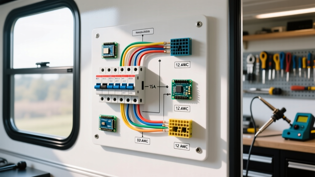
Using undersized wire on a charging circuit is the leading cause of voltage regulator burnout. According to the Engineering ToolBox AWG Reference, wire ampacity drops significantly when bundled or exposed to high ambient temperatures—exactly the conditions found under a mower hood. Below is the definitive gauge chart for B&S engine wiring.
| Circuit Type | OEM Wire Gauge (AWG) | Max Ampacity (Engine Bay) | Recommended Insulation | Typical B&S Application |
|---|---|---|---|---|
| Stator AC Output | 14 AWG (Min) | 15A - 20A | High-Temp Silicone / Cross-linked PE | Flywheel stator to regulator (AC legs) |
| Regulator DC Output | 12 AWG or 10 AWG | 20A - 30A | Standard PVC (SXL/THHN) | Regulator to battery positive / main harness |
| Regulator Ground | 12 AWG | 20A+ | High-Temp Silicone | Regulator casing/mount to clean engine block |
| Ignition Kill Switch | 18 AWG or 20 AWG | < 2A (Signal only) | Standard PVC | Magneto primary coil to chassis kill switch |
| PTO Clutch (Electric) | 10 AWG | 15A - 25A (Inrush) | SXL / Automotive Primary | Battery/Relay to electric PTO clutch coil |
| Starter Solenoid | 6 AWG or 4 AWG | 100A+ (Cranking) | Battery Cable / Fine Strand | Battery positive to starter motor via solenoid |
Why 12 AWG is Mandatory for the DC Output
Many DIYers attempt to use 14 AWG wire for the DC output of a 16-amp B&S stator (OEM Part #593998 or similar). While 14 AWG is technically rated for 15 amps in free air, the NFPA 70 (National Electrical Code) mandates heavy derating for wires in high-temperature engine enclosures. A 14 AWG wire running near a 400°F engine block will experience severe voltage drop and heat buildup, eventually melting the insulation and shorting against the chassis. Always use a minimum of 12 AWG, preferably 10 AWG, for the main DC charging line.
Standard Color Code Reference for B&S Engines
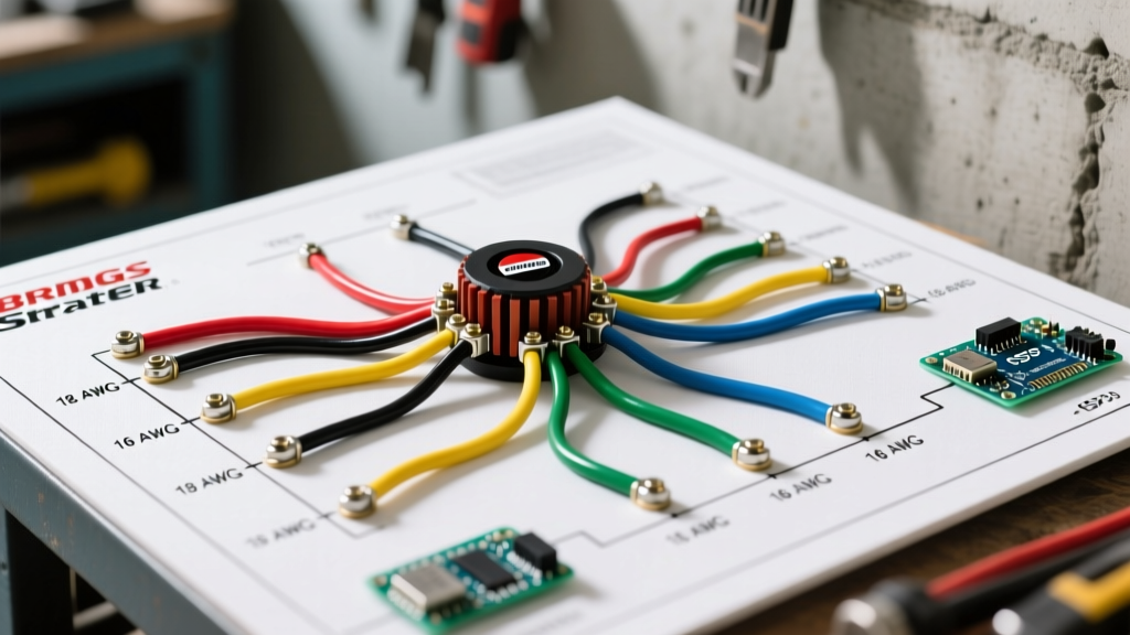
While aftermarket harnesses can vary, Briggs & Stratton maintains a relatively strict color code for their OEM stators and regulators. Identifying these wires correctly is crucial when referencing a generic wiring diagram for Briggs and Stratton engine applications.
- Yellow / Yellow (or Yellow / Black): These are the AC Stator Output Wires. They carry the raw, unrectified alternating current from the stator to the regulator. Polarity does not matter on these two wires.
- Red: The DC Positive Output from the voltage regulator. This wire routes directly to the battery's positive terminal or the main positive bus bar, usually protected by an inline 20A or 30A fuse.
- Black (or bare copper ring terminal): The Regulator Ground. On modern B&S regulators, the ground is often achieved through the metal mounting bracket touching the engine block. However, a dedicated black 12 AWG ground wire is highly recommended to prevent ground-loop failures caused by engine paint or corrosion.
- White (Spade Connector): The Ignition Kill Wire. This connects to the magneto's primary coil. When this wire is grounded via the ignition switch, it shorts the coil, stopping the spark and killing the engine.
Common Wiring Failures & Troubleshooting Edge Cases
Even with a perfect wiring diagram for Briggs and Stratton engine systems, physical degradation leads to specific, repeatable failure modes. Here is how to diagnose them like a master technician.
1. The 'Melted Regulator Connector' Syndrome
The Symptom: The plastic housing of the OEM 3-pin regulator connector melts, fusing the pins together, and the battery stops charging. The Root Cause: Micro-corrosion on the spade terminals increases electrical resistance. According to Ohm's Law (V=IR), higher resistance at a constant current generates massive localized heat. The Fix: Do not just replace the regulator. Cut off the corroded harness side. Solder in a replacement pigtail using high-temp silicone wire, and apply dielectric grease (like Amphenol DeoxIT) to the terminals before mating. In 2026, a high-quality replacement pigtail costs about $12, saving you from buying a $65 regulator.
2. AC Ripple Destroying the Battery
The Symptom: The battery boils dry, or the mower's LED headlights flicker violently at idle. The Root Cause: One of the diodes inside the regulator/rectifier has failed short. It is now passing raw AC voltage into the DC battery circuit. The Diagnostic Test: Set your multimeter to AC Volts. Place the probes on the battery terminals while the engine runs at 3600 RPM. You should read less than 0.5V AC. If you read 5V to 15V AC, your regulator has failed internally and must be replaced immediately to prevent catastrophic battery explosion.
3. The Phantom Ignition Kill
The Symptom: The engine backfires, misfires under load, or randomly shuts off when hitting a bump. The Root Cause: The 18 AWG white kill wire is chafing against the engine shroud or the kill switch itself has internal corrosion, intermittently grounding the magneto. The Fix: Disconnect the white wire at the magneto coil. If the engine runs perfectly, the fault is in the chassis wiring or the key switch. Inspect the wire routing under the blower housing—ensure it is secured with high-temp zip ties and routed away from the spinning flywheel fan blades.
Upgrading Your Harness: Silicone vs. PVC
When performing a full harness rebuild on a commercial B&S Vanguard engine, consider abandoning standard PVC (Polyvinyl Chloride) wire in the engine bay. PVC insulation becomes brittle and cracks when exposed to the continuous 180°F+ ambient temperatures of an air-cooled V-Twin engine block.
The 2026 Standard: Upgrade all stator and regulator wiring to High-Temp Silicone Wire. Silicone wire is rated for continuous use up to 392°F (200°C). Furthermore, silicone wire utilizes fine-strand copper (often 30 AWG strands inside a 14 AWG jacket), making it vastly more flexible and resistant to the high-frequency vibrations that snap the thicker, coarse strands found in cheap automotive wire. A 25-foot spool of 12 AWG silicone wire retails for roughly $18-$24, an insignificant investment for commercial uptime.
Frequently Asked Questions (FAQ)
Can I use a 16A stator with a 9A voltage regulator?
Technically, yes, but it is not recommended. A 9A regulator will clip the top of the AC waveform to maintain 14.4V, dissipating the excess energy as extreme heat. The regulator will likely fail prematurely. Always match the regulator's amperage rating to the stator's output. For official schematics and part compatibility, always consult the Briggs & Stratton Official Support Portal using your specific engine model and type code.
Why does my stator output only 12V AC?
The stator output is directly proportional to engine RPM. If you are measuring 12V AC, your engine is likely idling at 1500-1800 RPM. You must measure the stator output at the governed maximum speed (typically 3400 to 3600 RPM for a 60Hz generator or standard mower application) to get an accurate diagnostic reading of 28V-35V AC.
Do I need a fuse between the regulator and the battery?
Absolutely. A 20-amp inline ATC blade fuse should be installed on the red DC positive wire, as close to the battery positive terminal as possible. If the regulator fails short and sends unrectified AC or unregulated voltage toward the battery, or if the DC wire chafes against the chassis, this fuse will blow, preventing a catastrophic electrical fire.