
Understanding the Code-Compliant Wiring Diagram for Fan with Light
Installing a ceiling fan with an integrated light kit is one of the most common residential electrical upgrades, yet it remains a frequent source of code violations and fire hazards. As of 2026, the integration of smart home technology and high-efficiency DC motors has changed the load profiles of these fixtures, but the foundational safety requirements outlined in the National Electrical Code (NEC) remain strict. A proper wiring diagram for fan with light setups must account for independent switching, neutral availability, box fill volume, and physical weight support.
This guide breaks down the exact NEC-compliant wiring methodology for a standard dual-switch ceiling fan and light combination, prioritizing safety, structural integrity, and modern smart-switch compatibility.
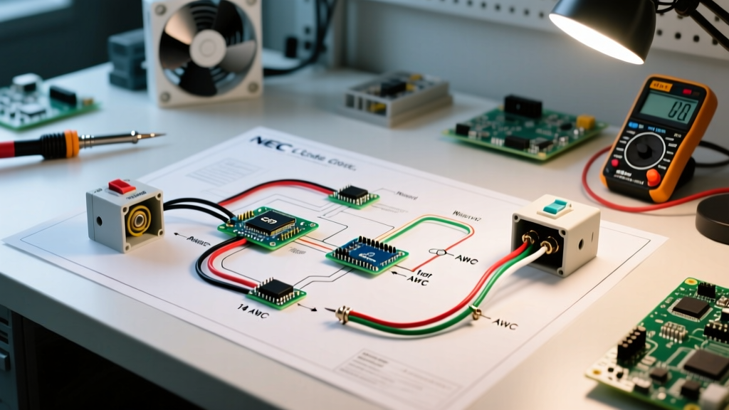
The Core Wiring Architecture: 14/3 NM-B Cable Standard
To control the fan motor and the light kit independently from a single wall switch box, you must run a 3-wire cable with a ground from the switch box to the ceiling receptacle box. For a standard 15-amp circuit, this requires 14/3 NM-B (Romex) cable. If the circuit is on a 20-amp breaker, you must upgrade to 12/3 NM-B.
Conductor Assignment Breakdown
- Black Wire (Hot 1): Carries switched power from the bottom switch to the fan motor receiver or canopy toggle.
- Red Wire (Hot 2): Carries switched power from the top switch to the light kit blue wire.
- White Wire (Neutral): Completes the circuit for both the fan and the light, connecting to the white fixture wires.
- Bare Copper (Ground): Bonds the metal ceiling box, the switch yoke, and the fan mounting bracket to the equipment grounding system.
Critical NEC Requirements for Fan and Light Combos
Following the wiring diagram is only half the battle. The physical installation must meet specific NEC articles to pass inspection and ensure long-term safety. According to the National Fire Protection Association (NFPA 70), inspectors focus heavily on three areas during ceiling fan installations.
1. Ceiling Box Weight Ratings (NEC 314.27(C))
Standard octagonal ceiling boxes are rated for static loads up to 35 pounds. However, ceiling fans generate dynamic torque and vibration. NEC 314.27(C) mandates that any ceiling box supporting a fan must be explicitly listed for fan support.
Expert Insight: Never rely on standard wood screws driven into a joist through a standard box. Use a listed fan-rated box like the Raco 937 (retail price ~$9.50), which features a threaded metal bracket that mounts directly to the joist and is rated for fans up to 70 lbs. For heavier models like the 72-inch Hunter Grand Cayman, you must use a structural brace rated for the specific weight.
2. Switch Box Neutral Requirements (NEC 404.2(C))
Historically, electricians used 14/2 cable for switch loops, sending a hot down to the switch and returning a switched hot (often re-identified with black tape) back to the fan. NEC 404.2(C) strictly prohibits this for new installations. You must provide a grounded neutral conductor at the switch box. This is why the 14/3 NM-B cable is mandatory; the white wire serves as the neutral for modern smart switches (like the Lutron Caseta or Kasa Smart series) which require standby power for their internal Wi-Fi/Zigbee radios.
3. Box Fill Volume Calculations (NEC 314.16)
Overcrowding a switch box with 14/3 cables and dual rocker switches causes heat buildup and crushed wire insulation. You must calculate the box fill volume. Let us calculate the required volume for the wall switch box controlling the fan and light:
- Conductors: 1 incoming hot (black), 1 outgoing hot to fan (black), 1 outgoing hot to light (red), 2 neutrals (white) = 4 current-carrying conductors.
- Equipment Grounds: All bare wires count as 1 allowance.
- Clamps: Internal cable clamps count as 1 allowance.
- Devices: 2 switches (a duplex rocker or two singles) count as 2 allowances each = 4 allowances.
Total Allowances: 4 + 1 + 1 + 4 = 10 allowances. For 14 AWG wire, each allowance requires 2.0 cubic inches. Therefore, you need a switch box with a minimum volume of 20 cubic inches. A standard single-gang box (18 cu in) is a code violation here; you must use a deep single-gang (22.5 cu in) or a double-gang box.
Step-by-Step Wiring Execution & Termination
Proper termination is where most DIY failures occur. The U.S. Consumer Product Safety Commission (CPSC) notes that loose connections are a leading cause of residential electrical fires.
Step 1: Prepare the Conductors
Strip exactly 11mm (7/16 inch) of insulation from the 14 AWG solid copper wires. If you are using Wago 221-413 lever nuts—which are highly recommended for their vibration resistance in ceiling fan applications—the strip length is critical. Too short, and the clamp bites the insulation; too long, and exposed copper creates a shock hazard.
Step 2: Terminate the Switch Box
- Connect all white neutral wires together using a lever nut. Pigtail a short white wire to the neutral terminal if using a smart switch.
- Connect the incoming hot (line) to the common terminal of both switches using a black pigtail.
- Connect the black load wire to the fan switch and the red load wire to the light switch.
- Terminate all bare ground wires to the green grounding screw on the metal box and pigtail to the green grounding screws on the switches.
Step 3: Terminate the Canopy (Ceiling Box)
At the ceiling, the wiring diagram simplifies. Connect the black and red wires from the 14/3 cable to the corresponding black (fan) and blue (light) wires on the fan harness. Connect the whites together and the grounds together. If your fan includes a remote control receiver module, it will typically install in the canopy housing; ensure the canopy has adequate cubic inch volume to house the module without pinching the 14/3 cable.
Reference Data: NEC Conductor Volume Allowances
When planning your installation, use this table derived from NEC Table 314.16(B) to ensure your selected electrical boxes meet the minimum volume requirements for the wire gauge you are pulling.
| Wire Size (AWG) | Volume Allowance per Conductor (Cubic Inches) | Typical Application |
|---|---|---|
| 14 AWG | 2.0 cu in | 15-Amp Lighting & Fan Circuits |
| 12 AWG | 2.25 cu in | 20-Amp Circuits / High-Draw Commercial Fans |
| 10 AWG | 2.5 cu in | 30-Amp Circuits (Rare for standard fans) |
Common Failure Modes and Edge Cases
Even with a correct wiring diagram for fan with light setups, specific edge cases can compromise safety:
- Shared Neutrals on Multi-Wire Branch Circuits (MWBC): If your fan and light are fed from an MWBC (two hots sharing one neutral), the neutral can become overloaded if both switches are on, unless the hots are on opposite phases. NEC 210.4 requires MWBCs to have a simultaneous disconnect (double-pole breaker or handle tie).
- Dimmer Incompatibility: Standard incandescent dimmers will destroy the integrated LED driver boards found on 2026-era ENERGY STAR certified fans. Always verify that the wall switch is rated for LED/CFL loads and matches the fan's specific driver requirements, as outlined by ENERGY STAR Ceiling Fan Specifications.
- Grounding Non-Metallic Boxes: If you are using a PVC ceiling box, you must still bond the equipment grounding conductor to the fan's metal mounting bracket. Do not leave the ground wire capped off inside a plastic box.
Final Safety Verification
Before energizing the circuit, perform a continuity test on the grounding path from the fan bracket back to the main service panel. Once power is restored, use a non-contact voltage tester to verify the canopy is completely de-energized when the switches are off. Proper adherence to this wiring diagram and the NEC guidelines ensures a safe, durable, and code-compliant installation that will withstand years of dynamic motor vibration and thermal cycling.