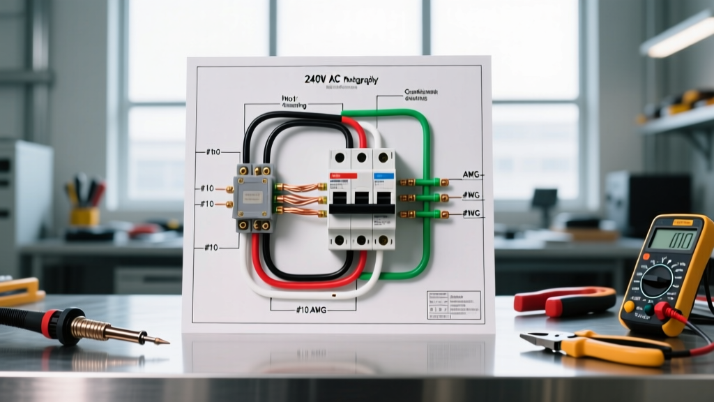

Understanding the Wiring Diagram for AC Disconnect Boxes
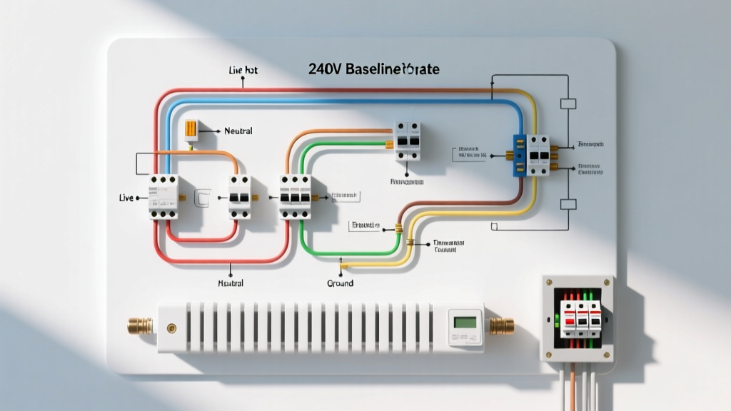
When installing or servicing a central air conditioning system, the outdoor disconnect box is a critical safety component. It serves as the local shut-off point for the condenser unit, allowing HVAC technicians to safely lock out power before performing maintenance. If you are searching for a reliable wiring diagram for AC disconnect setups, you must first understand that these 240-volt appliances require precise terminal mapping, correct wire sizing, and strict adherence to the National Electrical Code (NEC).
Whether you are wiring a non-fused pull-out style (like the widely used Eaton CU50) or a fused lever-style disconnect (such as the Siemens HNF324), the fundamental routing of line, load, and ground remains consistent. As of 2026, the average cost for a standard 60A non-fused pull-out disconnect ranges from $35 to $55, while fused models with time-delay cartridges typically cost between $80 and $120, excluding the fuses themselves.
Anatomy of an AC Disconnect Box
Before following any wiring diagram for AC disconnect installations, identify your box type. The internal architecture dictates how the feed and load wires are terminated.
- Line Terminals (Source): These connect directly to the double-pole breaker in your main electrical panel. In a pull-out disconnect, these are the fixed terminals that remain energized as long as the main breaker is ON, even if the pull-out block is removed.
- Load Terminals (Equipment): These connect to the outdoor condenser unit. Power only reaches these terminals when the pull-out block is fully inserted or the lever is switched to the ON position.
- Grounding Lug: A dedicated mechanical lug bonded to the metal enclosure for the Equipment Grounding Conductor (EGC).
- Pull-Out Block / Lever Mechanism: The physical bridge that connects the Line side to the Load side. Fused models house dual-element time-delay fuses on this bridge to protect against motor inrush current spikes.
Step-by-Step 240V Hookup Guide
Bypassing proper lockout/tagout procedures is a leading cause of electrical injuries in the trades. According to OSHA's lockout/tagout standards, establishing a verified zero-energy state is mandatory before touching any terminals. Always shut off the corresponding double-pole breaker in the main panel and verify with a non-contact voltage tester and a digital multimeter before proceeding.
1. Mounting and Conduit Preparation
Mount the disconnect box within sight of the condenser unit, typically on the exterior wall or a dedicated post. The NEC requires the box to be readily accessible. Run 3/4-inch Liquidtight Flexible Metal Conduit (LFMC) or Schedule 80 PVC from the disconnect down to the condenser whip. If using LFMC, ensure you use a waterproof liquidtight connector at the knockout to maintain the NEMA 3R weather-resistant rating of the enclosure.
2. Pulling the Conductors
Pull your THHN/THWN-2 copper conductors through the conduit. You will need four wires for a standard 240V split-phase AC circuit: Black (Hot 1), Red (Hot 2), White (re-identified as Hot 3, if required for specific control boards, though rarely used in modern pure 240V condensers), and a bare or green Equipment Grounding Conductor (EGC). For standard 240V-only condensers, you only need Black, Red, and Ground.
3. Terminating the Line Side (Main Panel Feed)
Route the feed wires from your main panel into the top or bottom knockout designated for the Line side. Strip exactly 5/8-inch of insulation for 10-8 AWG wire, or 3/4-inch for 6 AWG wire. Insert the Black and Red wires into the LINE lugs. Critical Step: Use a calibrated torque screwdriver to tighten the lugs to the manufacturer's specification, typically 20 to 25 inch-pounds. Loose lugs cause high-resistance connections, leading to arcing and melted disconnect blocks.
4. Terminating the Load Side (Condenser Whip)
Route the wires exiting toward the condenser into the LOAD side lugs. Connect the Black and Red wires to the load terminals. Just like the line side, torque these lugs to spec. Re-identify your wires with colored electrical tape at both ends if your local inspector requires strict phase-color adherence, though black and red are standard for 240V loads.
5. Bonding the Equipment Ground
Connect the bare or green grounding wire to the dedicated ground bus bar or grounding lug inside the disconnect box. This wire must be continuous from the main panel's ground bar, through the disconnect, and all the way to the condenser unit's grounding lug. Do not rely on the liquidtight conduit alone as your primary ground path; the NEC requires a dedicated wire-type EGC for HVAC equipment.
Wire Sizing and Breaker Matching Matrix
Selecting the correct wire gauge is dictated by the condenser's Minimum Circuit Ampacity (MCA) and the Maximum Overcurrent Protection (MOP) listed on the unit's data plate. Refer to the U.S. Department of Energy's HVAC guidelines to ensure your equipment sizing aligns with modern efficiency standards, which often dictate larger compressors and higher starting amps.
| Breaker Size (Main Panel) | Copper Wire Gauge (THHN) | Min. Ground Wire (EGC) | Disconnect Rating | Typical Condenser Tonnage |
|---|---|---|---|---|
| 20 Amp | 12 AWG | 12 AWG | 30A / 60A | 1.5 - 2.0 Tons |
| 30 Amp | 10 AWG | 10 AWG | 30A / 60A | 2.5 - 3.0 Tons |
| 40 Amp | 8 AWG | 10 AWG | 60A | 3.5 - 4.0 Tons |
| 50 Amp | 6 AWG | 10 AWG | 60A | 5.0 Tons |
Pro-Tip on Fusing: If your wiring diagram for AC disconnect setups requires a fused model, always use Dual-Element Time-Delay fuses (like Bussmann LPN-RK or Edison FRN-R). Standard fast-acting fuses will blow immediately when the compressor kicks on due to the Locked Rotor Amps (LRA) inrush current, which can be 5 to 7 times higher than the running amps.
NEC Code Requirements & Clearances (2023/2026 Cycles)
The National Fire Protection Association (NFPA 70) outlines strict rules for HVAC disconnects under Article 440. Compliance ensures both safety and passing municipal inspections.
Location and Working Space (NEC 110.26 & 440.14)
The disconnect must be installed within sight from and readily accessible to the air-conditioning equipment. "Within sight" means it must be visible and no more than 50 feet away from the condenser. Furthermore, you must maintain a minimum working space clearance of 30 inches wide and 36 inches deep in front of the disconnect box. Do not plant shrubs or build lattice fences that encroach on this 36-inch depth.
GFCI Receptacle Requirements (NEC 210.63)
While the 240V disconnect itself does not require GFCI protection, the NEC mandates that a 125V, single-phase, 15A or 20A GFCI-protected receptacle must be installed within 25 feet of the HVAC equipment for service tools. This receptacle must be on a separate circuit or properly protected, and it cannot be located on the load side of the equipment's disconnect switch.
Troubleshooting Common Disconnect Failures
Even with a perfect installation, environmental factors and mechanical wear can cause issues. Here is how to diagnose common problems:
- Melted Pull-Out Block Terminals: This is almost always caused by under-torqued lugs or using aluminum wire without proper anti-oxidant paste and CO/ALR rated lugs. The high resistance generates intense heat, melting the plastic housing. Fix: Replace the entire disconnect box; do not attempt to salvage melted components.
- Condenser Hums but Won't Start (Fused Models): One of the two cartridge fuses has likely blown, resulting in single-phasing. The compressor will hum, overheat, and trip its internal thermal overload. Fix: Test both fuses with a multimeter for continuity. Replace blown fuses with identical time-delay ratings.
- Water Intrusion and Corrosion: If the liquidtight conduit fittings were not sealed with silicone or if the box lid gasket is missing, rain will cause the copper lugs to oxidize (turn green/black). Fix: Clean terminals with a wire brush, apply Noalox antioxidant compound, and ensure the waterproof hub connectors are tightly secured.
Final Verification
Once all wires are terminated, the cover is replaced, and the pull-out block is inserted, turn the main panel breaker back ON. Use a multimeter set to AC Voltage to test across the Line lugs (should read ~240V), then test across the Load lugs (should also read ~240V). Finally, test from each Load lug to the Ground lug (should read ~120V each). If these readings are correct, your wiring diagram for AC disconnect execution is complete and the unit is ready for the HVAC technician to perform the final low-voltage thermostat wire hookup and refrigerant checks.