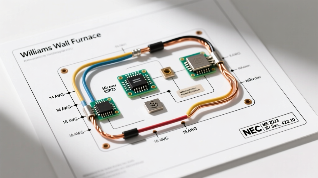

Decoding the Wiring Diagram for Williams Wall Furnace Installations
Williams wall furnaces, now manufactured under the Mestek umbrella, remain a cornerstone of heating solutions for older homes, garages, and room additions. Whether you are servicing a legacy unit or installing a modern replacement, interpreting the wiring diagram for Williams wall furnace models requires a strict adherence to both manufacturer specifications and the National Electrical Code (NEC). Unlike standard forced-air central HVAC systems, Williams units—particularly the ubiquitous Monterey and Forsaire lines—often utilize a hybrid of millivolt gas control and 120V blower circuits. This duality introduces unique safety and code compliance challenges that electricians and advanced DIYers must navigate carefully.
In this comprehensive guide, we break down the electrical architecture of Williams furnaces, map out the exact NEC articles governing their installation, and provide actionable wiring sequences to prevent catastrophic failure modes like induced voltage drop or thermal runaway.
System Architecture: Millivolt vs. 120V/24V Configurations
Before pulling any wire, you must identify the specific control architecture of your Williams unit. The wiring diagram for a Williams wall furnace varies drastically depending on whether it relies on a self-generating millivolt system or a standard 24V transformer setup.
| Feature | Monterey 3509622 (Millivolt) | Forsaire 5009632 (120V/24V) |
|---|---|---|
| Gas Valve Control | Thermopile (Generates ~750mV) | 24V Step-Down Transformer |
| Thermostat Wiring | 18 AWG Stranded (2-Wire) | 18-22 AWG Solid (Multi-Wire) |
| Blower Motor Power | 120V AC (Optional Kit) | 120V AC (Integrated) |
| External Power Required for Heat | No (Operates during outages) | Yes (Requires 120V branch circuit) |
| Primary NEC Focus | Article 250 (Grounding) & Low-Voltage Isolation | Article 422 (Appliances) & Article 430 (Motors) |
NEC Code Compliance Framework for Williams Furnaces
When executing the wiring diagram for Williams wall furnace setups, compliance with the NFPA 70 National Electrical Code is non-negotiable. Inspectors will specifically look for adherence to the following articles:
1. NEC Article 422: Appliances
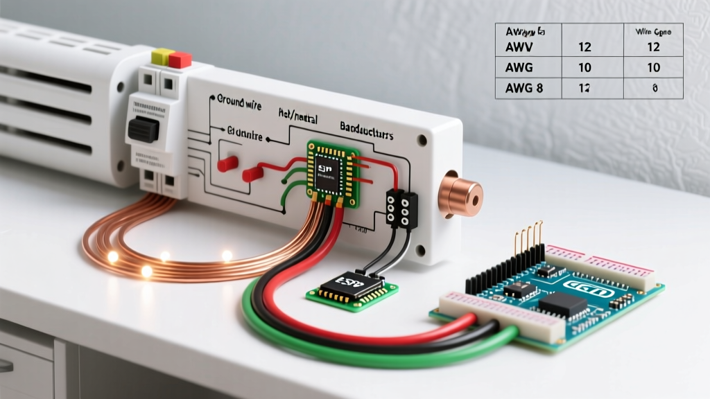
Williams wall furnaces with integrated or add-on blowers are classified as appliances. Under NEC 422.10, the branch circuit must be sized to handle 125% of the continuous load. A standard Williams blower motor draws between 2.5A and 4.2A. While a 15-amp circuit is technically sufficient, best practice dictates a dedicated 20-amp circuit using 12 AWG copper wire to mitigate voltage drop over long runs, especially in detached garages or additions.
2. NEC Article 422.31: Disconnecting Means
For units operating at 120V, the NEC requires a disconnecting means within sight of the appliance (not more than 50 feet away). If you are wiring a Monterey with a 120V blower kit, you must install a dedicated toggle switch or utilize a breaker lockout device at the main panel. Relying solely on the thermostat to break the circuit is a severe code violation and a major shock hazard for service technicians.
3. NEC Article 250: Grounding
Millivolt systems do not require a neutral or ground to operate the gas valve, but the furnace chassis and the 120V blower motor casing must be grounded. NEC 250.110 mandates that the equipment grounding conductor (EGC) be routed with the circuit conductors. Never rely on the gas pipe as a grounding path; this is both illegal and highly dangerous.
Step-by-Step Wiring Sequence: Monterey 3509622 with Blower
The following procedure outlines the safe execution of the wiring diagram for a Williams Monterey 35,000 BTU unit equipped with the optional 120V blower kit.
- Establish the Dedicated Branch Circuit: Run 12/2 NM-B (Romex) from a dedicated 20A single-pole breaker to a standard junction box located within 3 feet of the furnace. Install a 20A rated toggle switch to serve as your NEC-mandated local disconnect.
- Wire the Fan Control / Limit Switch: The Williams blower kit includes a bimetallic snap-disc limit switch. This switch closes at approximately 130°F to activate the blower and opens at 200°F to prevent overheating. Wire the 120V HOT leg (black wire) from your disconnect switch directly to the 'Line' terminal on the limit switch.
- Connect the Blower Motor: Run a wire from the 'Load' terminal of the limit switch to the HOT terminal on the blower motor. Connect the NEUTRAL (white wire) directly from the junction box to the motor's neutral terminal.
- Terminate the Equipment Ground: Connect the bare copper EGC to the green grounding screw on the blower motor casing, and pigtail it to the metal chassis of the Williams furnace.
- Route the Millivolt Thermostat Wires: Using 18 AWG stranded copper wire, connect the two terminals on the millivolt gas valve to your wall-mounted thermostat. Crucial: Keep these low-voltage wires at least 2 inches away from the 120V blower wiring to prevent electromagnetic interference.
CRITICAL SAFETY WARNING: Never bypass the factory-installed high-limit switch to force the blower to run continuously. According to the U.S. Consumer Product Safety Commission (CPSC), bypassing thermal limits on unvented or direct-vent wall furnaces can lead to heat exchanger warping, resulting in lethal carbon monoxide leaks into the living space.
Critical Failure Modes and Edge Cases
Even when following the wiring diagram for a Williams wall furnace perfectly, environmental and material factors can cause system failures. Understanding these edge cases separates novice installers from seasoned professionals.
The Millivolt Voltage Drop Trap
The thermopile on a Williams Monterey generates roughly 750 millivolts (mV) when heated by the pilot flame. The gas valve requires a minimum of 500mV to hold the main valve open. If an installer uses 14 AWG solid wire instead of 18 AWG stranded wire for the thermostat loop, the added mass and rigidity can create micro-tensions on the valve spade connectors. More importantly, running the millivolt wires parallel to 120V AC blower wires induces an alternating current noise that disrupts the DC millivolt signal. This results in the main burner 'chattering' or dropping out unexpectedly. Always route millivolt wires perpendicular to high-voltage wires when crossing is unavoidable.
Thermopile Degradation vs. Wiring Faults
When a Williams furnace fails to stay lit, DIYers often blame the wiring diagram or the gas valve. In 80% of cases, the issue is a degraded thermopile. Before tearing into the wiring, use a digital multimeter to test the thermopile output. With the pilot lit and the thermostat disconnected (open circuit), you should read between 650mV and 750mV. If the reading is below 550mV, replace the thermopile (Williams Part # P500-005) before adjusting any wiring.
Blower Motor Thermal Overload Tripping
If the 120V blower motor starts, runs for three minutes, and then shuts off, the internal thermal overload is tripping. This is rarely an electrical wiring fault. Instead, it indicates restricted airflow. Check the Williams-specific grille louvers and ensure the unit has the required 12-inch clearance from the floor. Blocking the lower return air intake starves the motor of cooling air, causing the amp draw to spike from a nominal 3.2A to over 6A, triggering the internal reset.
Expert Maintenance and Inspection Directives
To maintain long-term safety and compliance, integrate these checks into your annual HVAC maintenance routine:
- Spade Connector Tension: Millivolt systems are highly sensitive to resistance. Annually inspect the spade connectors on the gas valve and thermostat. If they feel loose, crimp them slightly with needle-nose pliers to ensure a tight, zero-resistance fit.
- Ground Continuity Test: Use a multimeter to verify continuity between the furnace chassis and the main panel's ground bus. A floating ground on a 120V blower kit can energize the entire metal casing of the furnace if the motor winding shorts.
- Wire Insulation Check: The ambient temperature inside the Williams furnace jacket can exceed 150°F. Ensure all internal 120V wiring is rated for at least 90°C (194°F). Standard 60°C Romex insulation will become brittle and crack over time when exposed to these internal temperatures.
Frequently Asked Questions (FAQ)
Can I use a smart thermostat with a Williams millivolt wall furnace?
Standard smart thermostats (like Nest or Ecobee) require a 24V 'C-wire' for power and will instantly destroy a Williams millivolt gas valve if connected directly. To use a smart thermostat, you must install a 24V step-down transformer and an isolation relay to separate the smart thermostat's 24V circuit from the furnace's millivolt circuit.
Does the NEC require GFCI protection for a Williams wall furnace blower?
Under the latest NEC guidelines, GFCI protection is generally not required for dedicated appliance receptacles or hardwired furnaces unless the unit is installed in a specific location like an unfinished basement, crawl space, or garage (depending on local amendments). However, hardwiring the unit with a local disconnect switch bypasses the receptacle GFCI requirement entirely and is the preferred method for Electrical Safety Foundation International (ESFI) compliance.
What happens if I reverse the hot and neutral on the 120V blower?
While the AC blower motor will still spin in the correct direction, reversing hot and neutral means the internal limit switch and thermal fuses will be breaking the neutral path instead of the hot path. This leaves the motor windings energized at 120V even when the switch is 'off,' creating a severe shock hazard during maintenance. Always verify polarity with a non-contact voltage tester.