
Mastering the RV Wiring Diagram for a 3 Speed Ceiling Fan
Upgrading the climate control in a motorhome, skoolie, or expedition vehicle often leads builders to a critical crossroads: how to effectively wire a ceiling fan without draining the house battery bank or overloading a pure sine wave inverter. Whether you are installing a native 12V DC brushless fan or routing a residential 120V AC unit through your rig's electrical system, understanding the correct wiring diagram for a 3 speed ceiling fan is paramount for safety and efficiency.
In 2026, modern RV electrical standards have evolved. The days of slapping solid-core Romex wire into a vibrating chassis are over. According to NFPA 1192 (Standard on Recreational Vehicles), all 12V DC wiring must utilize stranded copper wire to resist metal fatigue from road vibrations. This guide breaks down the exact wiring schematics, wire gauge calculations, and component selection for both 12V DC and 120V AC 3-speed ceiling fan installations in mobile environments.
12V DC vs. 120V AC: Which Fan Architecture Fits Your Build?
Before cutting into your RV's ceiling luan and styrofoam insulation, you must decide on the voltage architecture. Most 3-speed ceiling fans achieve their variable speeds through different mechanisms depending on their voltage.
| Feature | 12V DC Brushless Fan (e.g., Catalina, MaxxAir) | 120V AC Induction Fan (e.g., Hunter, Hampton Bay) |
|---|---|---|
| Speed Control | PWM (Pulse Width Modulation) Controller | Capacitor Bank or Smart Relay |
| Power Draw (High) | 1.5A - 2.5A (18W - 30W) | 0.5A - 0.8A (60W - 95W) |
| Wiring Complexity | Low (Direct to DC fuse panel) | High (Requires 120V AC breaker & inverter) |
| Vibration Tolerance | High (Lightweight, magnetic drive) | Low (Heavy motor, requires reinforced mounting) |
Step-by-Step: 12V DC Wiring Diagram for a 3 Speed Ceiling Fan
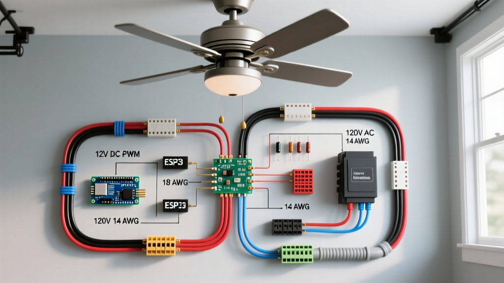
For off-grid campervans and skoolies, a 12V DC fan is the gold standard. The 3-speed functionality is managed by an inline PWM switch, which rapidly pulses the DC current to simulate lower voltages without generating the heat associated with old-school resistive rheostats.
Required Components
- Wire: 12 AWG Stranded Copper (THHN or GXL automotive wire).
- Overcurrent Protection: Bussmann ATC 10A Blade Fuse or Blue Sea Systems 10A Circuit Breaker.
- Switch: 12V 3-Speed PWM Rotary Dial (rated for minimum 5A).
- Connectors: Heat-shrink ring terminals and butt connectors (12-10 AWG).
The Wiring Sequence
- Source to Fuse: Run a 12 AWG red (positive) wire from your 12V DC distribution busbar to a 10A fuse holder. Mount the fuse within 18 inches of the busbar to protect the entire wire run.
- Fuse to PWM Switch: Route the red wire from the fuse to the 'IN' terminal on the 3-speed PWM wall switch.
- Switch to Fan: Connect a red wire from the 'OUT' terminal of the PWM switch up through the ceiling cavity to the fan's positive lead.
- Ground Return: Run a 12 AWG black (negative) wire directly from the fan's negative lead back to the negative busbar. Never use the vehicle's metal chassis as a ground return for high-draw or sensitive PWM electronics, as chassis grounding introduces voltage fluctuations that can cause the fan motor to stutter.
Pro-Tip for 2026 Builds: If your RV features a smart battery management system (BMS) with Bluetooth monitoring, wire the PWM switch's ground through a low-profile shunt. This allows you to track the exact amp-hours consumed by your ceiling fan via your rig's central monitoring app.
Step-by-Step: 120V AC Inverter-Powered Wiring Diagram
Luxury Class A motorhomes and fifth wheels often utilize residential 120V AC 3-speed ceiling fans. These fans use a capacitor-based speed controller (usually integrated into a pull-chain mechanism or a wall-mounted variable frequency drive).
The AC Wiring Sequence
- Inverter to Breaker: From your Pure Sine Wave Inverter's AC output, run 12/2 stranded marine cable (THHN/THWN) to a dedicated 15A AC breaker in your sub-panel.
- Breaker to Wall Switch: Route the 12/2 cable to a standard 3-speed fan control wall switch. The black (hot) wire connects to the switch's line-in terminal.
- Switch to Canopy: From the switch's load-out terminal, run the black wire to the fan canopy. The white (neutral) and bare/green (ground) wires bypass the switch and run continuously from the panel to the canopy.
- Canopy Connections: Connect the switch's hot wire to the fan's black/blue motor wire. Connect the panel's neutral to the fan's white wire. Bond the ground to the fan's mounting bracket.
Crucial Consideration: Voltage Drop and Wire Sizing
In a 40-foot motorhome, the distance from the battery bank to the ceiling fan can easily exceed 30 feet (60 feet total round-trip). Sizing your wire based solely on ampacity is a rookie mistake; you must size for voltage drop. A 12V fan receiving only 10.5V due to undersized wiring will draw excess amperage, overheat the PWM controller, and fail prematurely.
Using the Cerrowire Voltage Drop Calculator, we can determine the correct gauge for a 2.5A fan on a 14V system with a maximum acceptable drop of 3% (0.42V):
- 10 ft run (20 ft round trip): 16 AWG is sufficient (1.1% drop).
- 20 ft run (40 ft round trip): 14 AWG required (2.2% drop).
- 35 ft run (70 ft round trip): 12 AWG required (3.8% drop - borderline, consider 10 AWG for heavy-duty expedition vehicles operating in high-heat environments where wire resistance increases).
Common Failure Modes and Troubleshooting
Even with a perfect wiring diagram for a 3 speed ceiling fan, mobile environments introduce unique failure points. Here is how to diagnose the most common issues:
1. Fan Hums but Won't Spin on 'Low' Speed
Cause (120V AC): The start capacitor in the fan's canopy has degraded. AC induction motors require a phase shift from the capacitor to generate starting torque at low voltages.
Fix: Open the canopy, locate the small black rectangular capacitor, and replace it with an identical microfarad (µF) rating. Ensure it is secured with a zip tie to prevent it from rattling against the metal housing while driving.
2. PWM Switch Overheating and Shutting Down
Cause (12V DC): Voltage drop is causing the fan to pull higher amperage than rated, or the PWM switch is undersized for the fan's inrush current. Brushless DC motors can pull 3x their running amperage for the first 500 milliseconds during startup.
Fix: Verify your wire gauge using the voltage drop formula. Upgrade the PWM switch to a model rated for at least 10A continuous, even if the fan only draws 2.5A at steady state.
3. Intermittent Power Loss on Bumpy Roads
Cause: Use of solid-core wire or non-ratcheting crimp connectors. The vibration of the vehicle chassis causes solid wire to snap at the terminal, or poorly crimped wires to back out of the connector.
Fix: Cut out the damaged section. Strip stranded marine-grade wire using a precision wire stripper, and use a ratcheting crimping tool to apply adhesive-lined heat shrink terminals. The adhesive melts and seals the connection against moisture and vibration.
Frequently Asked Questions
Can I use a standard residential dimmer switch for a 12V DC fan?
No. Standard residential dimmers use TRIACs designed to chop AC waveforms. If you wire a 12V DC fan to an AC dimmer, it will either not work or short-circuit, potentially causing a fire. You must use a DC-specific PWM (Pulse Width Modulation) controller designed for inductive motor loads.
Do I need to ground the metal mounting bracket of a 12V fan?
Yes. While the 12V system is low voltage, NFPA 1192 and general RV safety standards dictate that any exposed metal chassis or mounting bracket that could inadvertently contact a frayed positive wire must be bonded to the negative busbar to prevent the metal from becoming energized and shocking the occupant.
Will running a 120V AC ceiling fan drain my RV batteries faster than a 12V DC fan?
Generally, yes. Aside from the higher base wattage of most residential AC fans, the inverter itself consumes 'no-load' power (typically 10W to 25W) just to remain on and convert DC to AC. For boondockers relying on solar, a native 12V DC fan is vastly more efficient for overnight use.