
Mastering the Electrical System: A Comprehensive Guide
Produced between 1947 and 1952, the Ford 8N remains one of the most iconic and widely restored vintage tractors in North America. With over 530,000 units rolling off the assembly line, finding a surviving model is easy, but resurrecting its electrical system requires precision. Whether you are maintaining a museum-quality original or upgrading for daily farm use, understanding the correct wiring diagram for 8N Ford tractor configurations is non-negotiable. In this 2026 updated guide, we break down the exact wiring schematics, component specifications, and conversion protocols for both 6-volt and 12-volt systems.
The Great Divide: Front-Mount vs. Side-Mount Distributors
Before pulling any wire, you must identify your tractor's specific architecture. Ford introduced a major design change mid-production, meaning the wiring diagram for 8N Ford tractor models depends entirely on your serial number.
- Front-Mount Distributor (Serial Numbers up to 263843): Produced from 1947 to mid-1950. This setup uses a unique square ignition coil mounted directly on the front of the distributor. The dash features a 4-post terminal block that acts as the central junction for the ignition, ammeter, and generator.
- Side-Mount Distributor (Serial Numbers 263844 and up): Introduced in late 1950 through 1952. This design moved the distributor to the side of the engine block, utilizing a standard round coil and eliminating the complex dash terminal block in favor of a more traditional, direct-wired ignition switch.
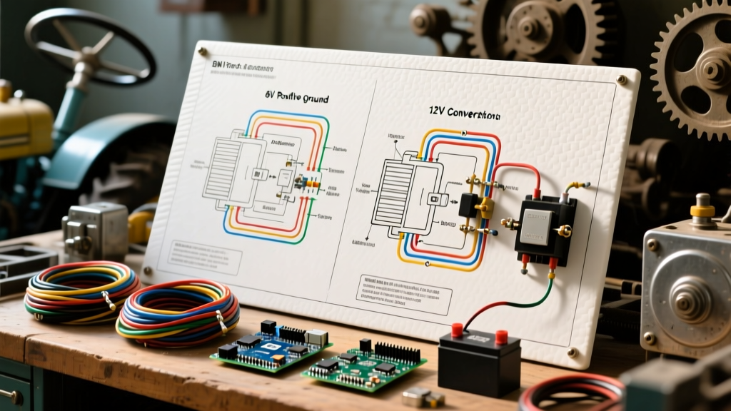
The Original 6-Volt Positive Ground Wiring Flow
If you are performing a strict OEM restoration, you must adhere to the original 6-volt positive ground system. While modern vehicles use negative ground, Ford utilized positive ground on the 8N to theoretically reduce electrolytic corrosion on the steel chassis—a common practice in the 1940s.
According to archival documentation preserved by the N Tractor Club, reversing the battery polarity on an original 6V 8N generator will cause the ammeter to read backwards and can severely damage the voltage regulator cut-out relay.
Step-by-Step 6V Routing
- Battery to Ground: The positive (+) terminal of the 6V battery connects to the tractor frame via a heavy braided ground strap.
- Battery to Starter: The negative (-) terminal routes to the starter motor solenoid and the starter switch on the dash.
- Ammeter Integration: The main heavy-gauge wire from the starter switch routes to the 'BAT' terminal on the back of the loop-type ammeter. The 'GEN' terminal on the ammeter then routes to the voltage regulator and the ignition switch.
- Ignition Circuit: Power flows from the ammeter to the ignition switch, then to the ballast resistor (if equipped), and finally to the negative terminal of the square coil.
The 12-Volt Negative Ground Conversion Diagram
As of 2026, the vast majority of working 8N tractors have been converted to 12-volt negative ground systems. This conversion vastly improves cold-weather cranking, allows for modern LED lighting, and makes sourcing replacement alternators trivial. The most popular alternator swap is the Delco 10-SI (63-Amp or 94-Amp), which costs between $45 and $75 at most auto parts stores.
Wiring the Delco 10-SI Alternator
When adapting the wiring diagram for 8N Ford tractor 12V conversions, the alternator wiring is the most common stumbling block. The 10-SI features a 2-pin connector and a main BAT output post.
- BAT Terminal: Run a 10 AWG wire directly from the alternator BAT post to the 'GEN' or 'ALT' side of the ammeter. Do not route this through the ignition switch.
- Terminal #1 (Excite): This wire must be connected to the ignition switch's 'IGN' terminal. It provides the initial excitation voltage to start the charging process. Crucial: You must wire an inline 10-ohm, 2-watt resistor or a 194-style incandescent dash light into this wire to prevent feedback that will keep the tractor running after you turn the key off.
- Terminal #2 (Sense): Jump this terminal directly to the alternator's main BAT post to allow the internal regulator to sense system voltage accurately.
Upgrading the Starter Motor for 12V
Many DIYers convert to 12V but leave the original 6V starter motor in place. While a 6V starter will spin on 12V, it will draw nearly double the amperage (often exceeding 250A), generating excessive heat and prematurely destroying the Bendix drive and armature windings. For a reliable 2026 build, invest in a dedicated 12V starter motor (typically $85-$110). This ensures proper cranking RPM without thermal degradation, and it allows you to safely utilize modern 12V thin-wall battery cables.
Wire Gauge and Component Specifications
Adhering to proper ampacity standards is critical to prevent electrical fires. The following table outlines the required wire gauges based on NFPA 70 (National Electrical Code) guidelines for automotive and agricultural DC applications.
| Circuit / Component | Recommended Wire Gauge (AWG) | Max Ampacity / Load | Terminal Type |
|---|---|---|---|
| Battery to Starter Motor | 2/0 AWG (Welding Cable) | 200A+ Surge | 3/8" Ring Terminal |
| Main Harness (Battery to Ammeter) | 10 AWG | 30A Continuous | #10 Spade / Ring |
| Alternator BAT to Ammeter | 10 AWG | 65A (with 10-SI) | 1/4" Ring Terminal |
| Ignition Switch to Coil | 14 AWG | 5A | Piggyback / Spade |
| Headlights & Taillight | 14 AWG or 12 AWG | 15A Total | Bullet Connectors |
Common Failure Modes and Troubleshooting
Even with a perfect wiring diagram for 8N Ford tractor setups, age and vibration introduce specific failure modes. Here is how to diagnose the most frequent issues encountered in the field.
1. The "Runaway" Tractor (Alternator Feedback)
Symptom: You turn the ignition key off, but the engine continues to run and the alternator keeps charging.
Cause: Missing or bypassed excite resistor on the Delco 10-SI Terminal #1. The alternator is feeding 12V back into the ignition coil, bypassing the switch.
Fix: Install a 10-ohm ceramic resistor in the excite wire, or wire a standard 12V dash indicator bulb in parallel.
2. Ammeter Pegged to Discharge
Symptom: The needle pins to the left (discharge) immediately upon starting, even at high RPM.
Cause: If running a 6V generator, it has lost its residual magnetism and needs to be "polarized." If running a 12V alternator, the main BAT wire is routed to the wrong side of the ammeter, or the alternator diode trio has failed.
Fix: For generators, briefly touch a jumper wire from the BAT terminal of the voltage regulator to the GEN terminal while the engine is off. For alternators, swap the ammeter loop direction or test the alternator output with a multimeter (should read 13.8V - 14.4V at 1500 RPM).
3. Severe Voltage Drop Under Load
Symptom: Headlights dim significantly when the PTO is engaged or the engine is under heavy load; starter cranks sluggishly even with a fully charged battery.
Cause: Poor chassis grounding. The 8N relies on the engine block to frame ground strap, and the steering column to frame ground for the dash switch. Decades of paint, rust, and grease act as insulators.
Fix: Remove the braided ground strap from the front engine mount to the frame. Use a wire wheel to strip the metal down to bare steel on both the block and the chassis. Reinstall using star washers to bite through any future surface oxidation. Apply dielectric grease over the connection to prevent moisture intrusion.
Sourcing OEM vs. Aftermarket Wiring Harnesses
Building a harness from scratch using bulk wire and crimpers is possible, but purchasing a pre-loomed, cloth-braided harness saves hours of labor and ensures period-correct aesthetics. As of 2026, premium harnesses from suppliers like Steiner Tractor Parts or Brillman Company range from $75 to $130, depending on whether you need the front-mount or side-mount configuration.
- Front-Mount Harness: Includes the complex 4-post terminal block wiring and specific cloth loom for the square coil. Expect to pay around $115.
- Side-Mount Harness: Simpler routing, standard round coil leads. Typically costs around $85.
- Lighting Harness Add-on: Original 8Ns often lacked factory lights. If your tractor has the 3-position dash switch and sealed beam headlights, ensure you purchase the extended harness with the integrated light switch pigtails.
Final Thoughts on 8N Electrical Restorations
Successfully rewiring a Ford 8N requires respecting the original engineering while safely integrating modern upgrades where necessary. Whether you are strictly adhering to a 6-volt positive ground schematic or executing a robust 12-volt alternator conversion, the key lies in proper wire gauge selection, secure grounding, and understanding the specific distributor architecture of your serial number. Keep your wiring diagram for 8N Ford tractor references handy, use a digital multimeter to verify continuity before applying power, and your 8N will provide reliable electrical service for decades to come.